
OVERHAULING THE LAST OF THE QUADRAJET CARBURETORS PT. 4
We Were Able to Work With the Enclosed Idle Mixture Screws, But Encountered a Cutting Problem While Trying to Install the Secondary Shaft Bushings.
Time To Shed Light On Those Idle Mixture Screws

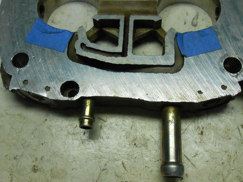
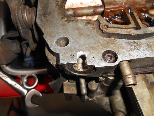
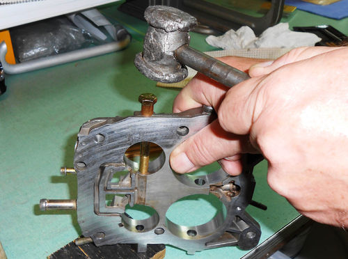
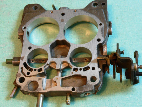
The idle mixture screws are secured with harden steel plugs. Photo 82 shows a close view of one in the throttle body. These plugs are very likely to shatter when you follow the recommended removal procedure, but the one in Photo 83 came out fairly intact from my swap meet carburetor. Those dots you see on the forward edge of the throttle body in Photo 84 are locator points for making saw cuts. The service manual’s removal procedure is to make two parallel cuts with a hacksaw in between each of these two locator points. Cut down to the hardened plug, but no more than 1 ⁄8" beyond the locator points. Then place a flat punch of the proper width near the end of the saw cuts, and with the aid of a hammer break out that small section of aluminum exposing the hardened shell. Finally using a hammer and sharpened center punch strike at the exposed shell. It will eventually shatter and break apart. Remove the broken pieces and make sure it’s open enough so that a mixture adjusting tool can fit into the well comfortably. I did this on the swap meet carburetor, and while it worked, it looked poor as seen in Photo 85.

I decided to try a different approach and grind out the end of the plug using a Dremel tool. Initially a small diameter cut-off wheel was used to make a couple of cuts 90° apart until a tiny hole appeared as seen in Photo 86.That was as far as the cut-off wheel could be used before making unwanted cuts in the throttle body.

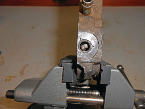
Next a coarse, cone-shaped grinding stone was used to work down the high spots and start to concave the area. Photo 87 shows the hole starting to enlarge. Continuing with the cone-shaped stone eventually completely opened the end of the plug as you see in Photo 88. While the shell still remains in the well, there is plenty of room for the adjusting tool to fit, and allow the mixture screws and spring to be removed. To make sure there was no lip or edge remaining, a pick tool with a slight hook on the end was placed in the well and then pulled out slowly to check smoothness.
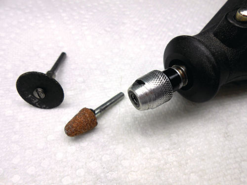
It’s just a matter of preference, but no doubt this has a much better look to it. As for time, each procedure took about the same amount. Photo 89 shows the tools that were used to do the job. A slight variation was used to grind out the second plug. Instead of making cuts with the cut-off wheel, it was passed back and forth over the raised end of the plug grinding it down equally until it finally started to concave and the hole appeared. This was a faster method, and left less work for the cone-shaped stone to finish up.
There are still a few more things to do here. The idle mixture wells are probably half full of abrasive dust, grit and fine metal grindings, so the throttle body was tipped upside down and tapped on the work bench to dislodge at least some of it. Next low-pressure compressed air was directed into the wells to gently dislodge some additional junk. Finally, carburetor cleaner spray was used to rinse out both wells.
Before removing the mixture screws and springs, it doesn’t hurt to know how many turns they are from their seated position. To make them thread more easily, each screw was backed out three turns and then WD-40 sprayed into each well. The screws were then threaded back in three turns to their original location, and then while counting the turns each mixture screw was gently brought to its seat. A written note of the number of turns was made. Be cautious about over-tightening the mixture screws due to the risk of breaking off the needle’s tip. It can certainly happen. Finally, remove each mixture screw and while it certainly isn’t necessary, it won’t hurt to bag each one with its spring and identify it as right or left. A note with the turn information was also placed in with each. In this case each was 2½ turns from the seated position.
With the steel mixture needles removed, it’s time to wash the throttle body. A sink with Dawn, hot water, a nylon bristle brush and a rag were used to remove any remaining abrasive. Once satisfied, it was rinsed and blown out with compressed air. The passages as well as surfaces of the throttle body were then sprayed with carburetor cleaner and again blown out with compressed air.
The swap meet carburetor posed another obstacle as the mixture needles were reluctant to turn. WD-40 was applied and eventually the right-side mixture screw came out. Being so tight to turn, no attempt was made to seat the needle as it would have been difficult to feel. The left side offered more resistance and when it came out, a small amount of aluminum from the throttle body came out with it. If I had it to do all over again, heat would have been applied to the throttle body in an effort to break that galvanic action between the steel and aluminum.
All that remains is to repair the threads with a tap. There isn’t a metric tap that tiny (M4 x 0.5) in my tool box or available locally, so one was ordered online. Actually, both a tap and die were ordered. Not being 100% sure about the size, the die will allow me to verify the thread size and pitch by first threading it onto an old mixture needle.
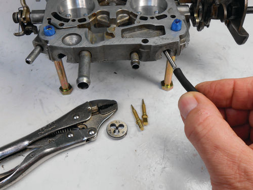
As it turned out, the order was coming directly from China and took several weeks to arrive. The majority of that time was due to a delay here in the US; probably at Customs. The die fit the threads of the mixture needle perfectly and actually cleaned them up to where they could be used again if needed. The tap was then used to clean up the threads as seen in Photo 90. Also in the photo you can see the die, replacement brass mixture screws and miniature Vise Grips. A piece of tiny windshield washer hose was used to start and rotate the tap. When the tap eventually started to slip in the hose, the miniature Vise Grips were used to rotate it. My small “T” handle tap holder wasn’t small enough, and wouldn’t close down sufficiently to hold the tap. The other long-arm holder held it fine, but wouldn’t clear the vacuum tubes sticking out of the throttle body. With the threads now clean, the springs from the old mixture screws are placed on the new screws, and they are gently bottomed and then backed out 3 turns each as per the factory service manual.
Reaming and Installing Primary and Secondary Shaft Bushings
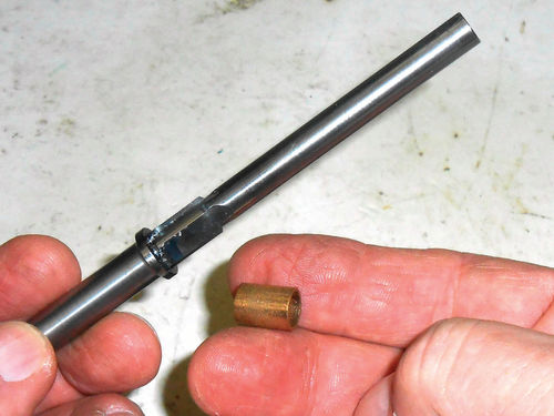
The primary throttle shaft is 5⁄16" diameter while the secondary is 3⁄8", so two different tools are required. Photo 91 shows the Zako-ATS 5⁄16, a special piloted cutting tool designed with a depth stop and one of the two bronze bushings that will be installed on the primary side. This tool was purchased about four years ago when overhauling the TBI (Throttle Body Injection) unit on our El Camino. It was ordered from Express Automotive Centre in Red Deer,Alberta, Canada; T4N 2T1; www.throttleshaftrepair.com. It’s an expensive tool, costing around $200 when you include shipping. Keep in mind that this tool is job specific. Its purpose is only for resizing carburetor (and TBI) worn throttle shaft holes. The long end of the tool is the 5⁄16" pilot followed by the four-edged cutter and the shoulder which is the depth stop. It does include instructions. They also offer the larger 3⁄8" version. Don’t be too quick to dismiss this tool. If you think you are likely to encounter other re-bushing tasks, or have other car friends to share in the expense; it’s an excellent tool and is pretty much fool proof to use.
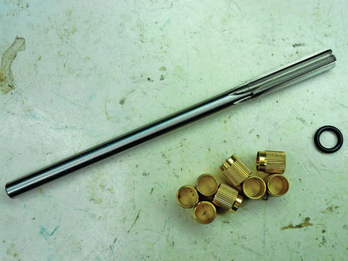
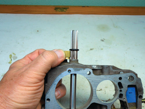
Photo 92 shows the ream tool and bushings for the 3⁄8" secondary shaft, purchased on eBay from Carb Junky’s out of Roberta, Georgia (www.carbjunkys.com). It was on sale for less than $40 and is likely one of the least-expensive tools to do the job. While it does not come with instruction, there is a note with the tool that states if you have questions about using it, to contact them. This is actually a 7⁄16" ream, but is used in an unconventional way. Photo 93 shows several things. First, the end of the ream that would normally be chucked in the drill is inserted as though it were the throttle shaft, acting as a pilot. As you will see later, the cutting flutes sticking out at the end are chucked into the drill or drill press. But whichever tool you choose to use, it must have a reverse setting, because that’s the only way it will cut with this set-up. There is no depth stop, and while you could mark the shaft with a Sharpie or wrap it with tape, I chose to use an inexpensive, snug-fitting plumbing O-ring instead. With the bushing against the shoulder of the throttle body, the rubber O-ring is pushed onto the reamer just above it, allowing it to cut slightly deeper. The O-ring is very easy to see and there will be lubrication used during the cutting process that could loosen tape or remove a Sharpie mark. They also offer a similar ream tool for 5⁄16" shafts.
There are other tools out there as well. One uses a drill bit instead of a ream to enlarge the throttle shaft holes. Drill bits yield a considerably rougher cut than a ream and tend to wander. While it might work just fine, the smoother, truer cut of a ream would seem to provide a much better environment for bushings.
To get started, the throttle body was clamped down securely to a work table in preparation for reaming the shaft holes. If you are using a vise, make sure to soften the bite with pieces of wood to avoid damaging the aluminum throttle body. Something as simple as doubled-up paint stir sticks will do.


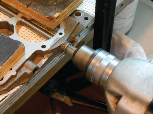
The primary side will be done first using the Zako-ATS cutter chucked into a ½” drill as seen in Photo 94. Using an appropriate slow RPM the tool cuts easily, and when the stop shoulder reaches the throttle body, you are done. As suggested, WD-40 was used during cutting, and the tool was pulled out several times to remove the accumulated chips. The throttle body was rotated to access the other primary shaft hole; re-clamped and the procedure repeated.
With all the cutting completed, and the chips removed; Photo 95 gives a glimpse of one of the smoothly reamed shaft holes.

The bushings are installed using the aid of a 5 ⁄16" bolt at least 3" in length. Slide the bushing onto the bolt so that it’s up against the bottom of the head, and insert the bolt through the shaft hole as though it were the throttle shaft. With the opposite shaft hole resting on a block of wood, the head of the bolt is tapped to insert the bushing as seen in Photo 96. When the bushing is flush, it’s fully installed as you see in Photo 97. The bushing installation for the other side is identical.
In Photo 98 the throttle shaft is temporarily slid in place to check the fit. All is fine, so service on the primary side is complete.
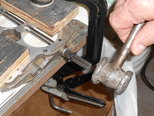
The procedure for the secondary side differs due to the tool used. The ream will actually be cutting with its back edge while driven in reverse. When speaking with Carb Junky’s, they advised if using a handheld drill, install the ream and give it a strike or two on the end with a hammer as seen in Photo 99. This will cause the cutting flutes to make several nicks in the shaft hole, giving the ream something to catch, and make it start cutting more easily.
With the drill switched to reverse, the chuck is tightened around the cutting flutes at the ream’s end. Oil was applied and I was prepared for the cutting action, but the absence of chips in Photo 100 is a pretty good indication that there was none.
I repeated the entire procedure again, but still no cutting. The first thought was the drill wasn’t in reverse, but that wasn’t it. Possibly if it had been removed from the work table set-up and secured in a bench vise with the shaft hole skyward things might have worked. After all, gravity would be adding a bit more downward pressure. No doubt plenty of other people have done this by hand.
So what is making it tough to begin with? First, the ream is being asked to remove a fair amount of material, 1 ⁄16". While that’s absolutely nothing for a drill bit, it’s a little more difficult for a straight-fluted ream. Second, attempting to cut with the back end of the ream you don’t have the advantage of any “lead in” on the tool. Look at the normal cutting end that’s chucked in the drill and you will notice a very slight angle on the cutting flutes. This is a big assistance in encouraging it to start cutting.
Next, we’ll turn to a drill press to see if it can be used to accomplish this cutting procedure.


