
OVERHAULING THE LAST OF THE QUADRAJET CARBURETORS PT. 2
We’re Busy Removing Parts From Our Quadrajet. Be Sure You Have a Good Supply of Bags on Hand for This Portion of the Project.
Editor’s note: GM used the Quadrajet 4-barrel carburetor for a quarter century. The last versions, used in the 1980s, were designated as GM’s Computer Command Control carburetors. This series will cover a complex overhaul of one of those famous carbs. The first installment had 16 photos so we’ll start here with Photo 17.
Disassembling the Carburetor

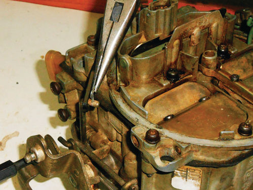
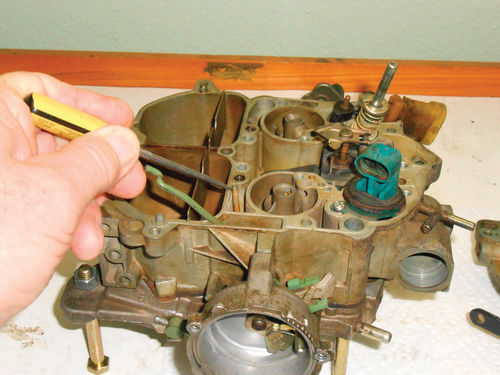
Photo 17 points to one of the two rivets that will be drilled out to remove the idle air bleed valve cover. This is nothing more than a formed piece of sheet metal located in the highest part of the air horn. Its removal will allow access to the Idle Air Bleed Valve (IABV) for service and making adjustments during reassembly.

A 7 ⁄64" or #35 (.110") drill bit will be used to perform this task. Photo 18 shows masking tape has been applied over the choke plate and surrounding area to help keep metal chips from entering the carburetor. This is actually suggested in the factory service manual. However, since a complete overhaul is being performed, this step isn’t necessary. Everything will be taken apart and cleaned, so any chips that enter the carburetor will be cleaned out. But then a little extra caution never hurts.
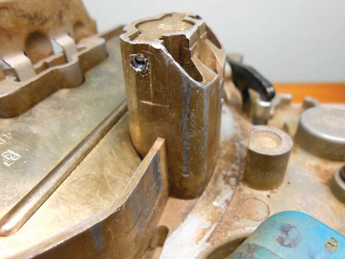
The rivet heads were drilled off as seen in Photo 19 and then a small punch was used to drive in the rivets in Photo 20. The rivets did push inward, but were still hanging on enough so that the cover plate couldn’t be removed. So the drilling continued. Photo 21 shows two things; first the additional drilling allowed the cover to be removed and secondly I carelessly grazed the top of the air valve with the drill bit. The air valve should be just fine, but if not, it will be replaced; possibly with the one from the parts carburetor if it’s not re-buildable. If you decide to remove the IABV now, use a straightblade screwdriver and first bottom the valve counting the turns from its current location. Make a written note of this for possible future reference. Very possibly you may not need this, but if you don’t have the information you are out of luck as I was. There will be more on my experiences much later in the article. That cover plate that was removed won’t be reused, so it can now be discarded.
Reach for the Bags
A good way to stay organized is to store the removed parts in zip lock bags. The small “snack size” zip locks are handy for most of the items. A piece of masking tape can then be used to label its contents. Combining like items where possible (for example “choke related”) will keep things manageable, organized, and reduce the number of bags you will have floating around. Having several of the larger sandwich bags will be handy, and three larger gallon-size can each hold the air horn, throttle body and fuel bowl. These parts can either be cleaned when removed prior to bagging or before reassembly. Washing the particularly dirty stuff first is a good choice.

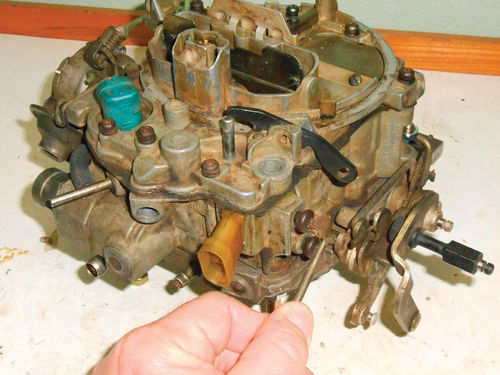
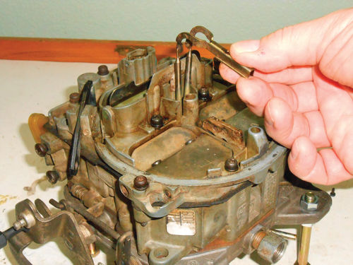
Continuing with rivet removal, let’s remove the choke thermostat. If it’s been replaced, it may have screws like those in Photo 22. In this event, just remove the three screws and wiggle the thermostat until in comes out. Otherwise use a #21 or 5 ⁄32" drill bit and drill off the rivet heads. Next use the appropriate diameter punch and drive the remainder of the rivets out. The thermostat is now free to be pulled out. Note the notch in the choke thermostat being pointed to in Photo 23. This corresponds with an index boss located on the inside of the forward screw hole. There is only one position that this thermostat can be mounted. It’s not like the older models where the thermostat could be rotated to richen or lean the choke. It’s all about controlling emissions.


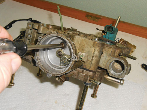
We are working toward removing the air horn, so next the choke shaft lever seen in Photo 24 will be removed and disconnected from the choke valve. This is easily accomplished by removing the retaining screw with a straight blade screwdriver and then manipulating it off, leaving the choke rod as shown in Photo 25. On the other side, Photo 26 shows a pair of needle nose pliers being used to remove the pump link retainer. To remove the link, partially open the throttle and rotate the link until the notch lines up and can be removed as in Photo 27. A T-8 Torx bit is used to remove the secondary metering rod holder screw seen in Photo 28. With the screw out, the metering rods and holder can be lifted out as shown in Photo 29. The vacuum break is located on the fuel inlet side of the carburetor. Removing the short vacuum hose and then the two retaining screws with a T-20 Torx driver frees the vacuum break.
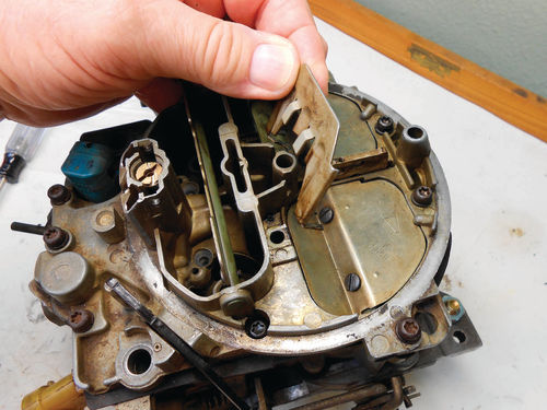
To disconnect the air valve rod from the shaft, rotate the rod 90° so that it’s straight up. This will align the end of the rod with the slot in the air valve shaft as seen in Photo 30 and it can now be removed.
A Quick Vacuum Test

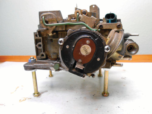
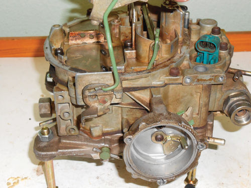
Now is a good time to test the vacuum break. If it is not functioning properly it can be the first item on the parts-needed list. Photo 31 shows a hand vacuum pump being used to apply 15" Hg vacuum. This should retract its plunger fully. Push on the plunger with your finger to verify it’s fully seated. It should maintain the vacuum for at least 20 seconds; if not, replace it. This one checks fine, but my swap meet carburetor needs a replacement. Note that some vacuum breaks have a vacuum bleed hole located somewhere in the diaphragm’s metal housing. If so, it must be plugged before performing this test and masking tape is usually a good choice for this task. The various types of vacuum breaks are shown in the manual. Don’t spray carburetor cleaner on this; instead brush it off and then spray some cleaner on a rag and wipe off anything that remains.

Both the fuel filter nut and fitting adapter on the back of the throttle body were loose and easily threaded out at this time. All that remains are 13 screws holding the air horn to the fuel bowl and if you look closely in Photo 32 you might spot 12 of them. If you’re missing some, notice that there are two smaller countersunk screws located below the choke valve on the primary side. There also is a screw at the top and bottom of the photo on the edges of the air horn.
Note that the two screws located to the far right, just behind the air valves, are 3" in length and pass through clearance holes in the fuel bowl. They actually thread into the throttle body. The remaining nine screws are all the same, so there is no chance of confusion due to length.

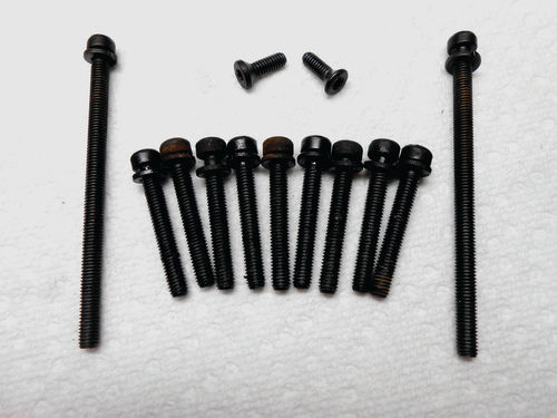
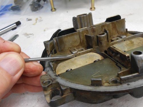
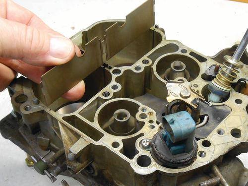
In Photo 33 a T-20 driver is used to remove the two small countersunk screws. The remainder of the air horn screws require a T-25 bit or driver. When the two central screws are removed it also frees the secondary air baffle as shown in Photo 34. For reference, here are all the air horn screws in Photo 35.
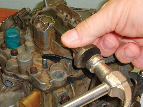
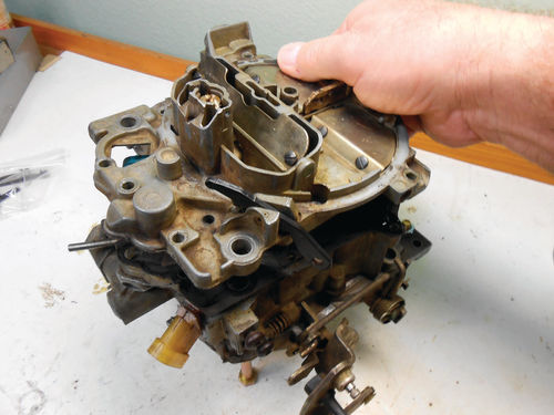
A little tap to the overhanging corner of the air horn releases it from the gasket. Lifting it straight up while guiding it to clear the choke rod will remove the air horn as seen in Photo 36. Do not attempt to lift off the gasket with the air horn.
Photo 37 shows what you can expect to see once it’s opened. While staring at the cover gasket, now is a good time to mention not to dispose of any old gaskets or parts until the job is completed. If there is any question you will have them for comparison purposes. It’s not unusual for a kit to include several of what may at first appear to be the same gasket. This allows the kit to cover more applications, but can add some confusion. In that event, having the original gaskets for comparison is a time saver.
Next the gasket is removed with some minor manipulation.
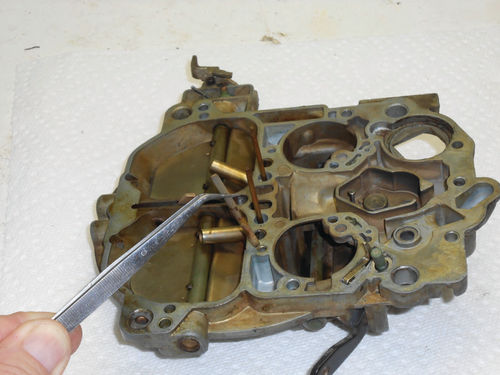
Photo 38 shows something unexpected. Lying loose in each secondary accelerator well are the secondary accelerator well tubes. The pick tool is pointing to one of them. These are small brass tubes—1 3 ⁄8"—long that should both be pressed up in the air horn. Photo 39 shows where one should be and the other fits on the opposite side. These tubes will supply fuel from the secondary accelerator wells when the secondary air valves are just starting to open.
Photo 40 points out the discharge orifice just above the air valve.
Once the air valve opens past this port, the pressure differential will draw fuel up from the wells into the secondary bore.
This supplements fuel until it’s supplied from the much larger secondary discharge nozzles (those large tubes at an angle below the air valves in Photo 39) and eliminates any stumbling on heavier acceleration.
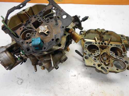
Working With the Fuel Bowl
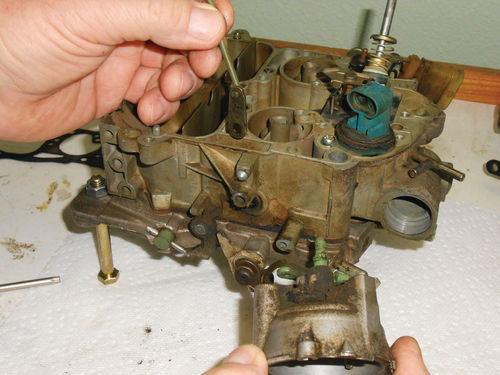
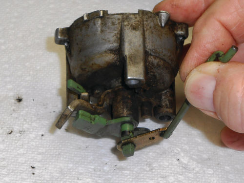

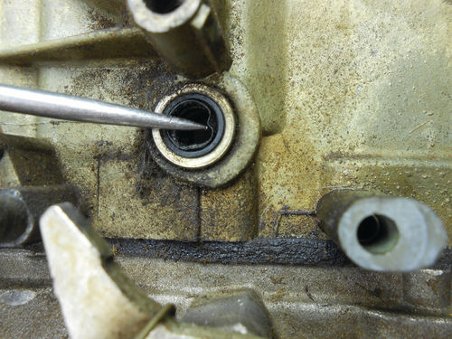
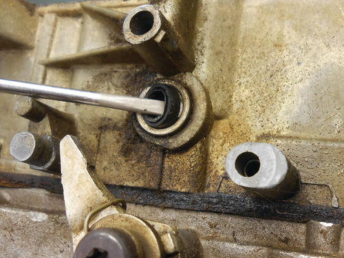
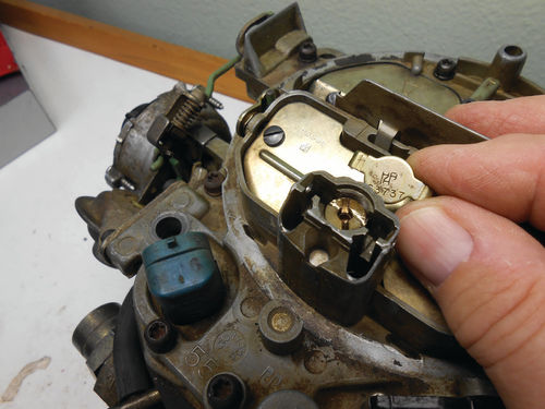
For now the focus will be on the fuel bowl; the air horn will be set aside until later in the project. Photo 41 shows a T-25 driver being used to remove the one retaining screw in the choke housing. While holding the choke rod, wiggle the choke housing slightly and pull straight out. If there’s resistance, work the throttle shaft back and forth as it’s likely caught on the fast idle cam. Now lift out the choke rod with the lever attached as seen in Photo 42. The lever just slips onto the rod (so it can easily fall off) and then fits over the shaft from the choke housing as shown in Photo 43. Becoming aware of this lever’s angle in relationship to the choke housing will make reassembly easier. It should make no difference if the lever is flipped over and replaced onto the shaft. Although seeing as it’s marked with the letter “B” on the side facing away from the float, it’s easy enough to remember and will be replaced the same way. The tweezers are lifting off the secondary lockout lever from its boss in Photo 44. It’s not unusual for it to fall off on its own once the choke housing is removed. This keeps the secondary throttle valves from opening until the choke is completely open. Photo 45 takes a closer look at the choke shaft seal. Note that its lip faces outward. Minimal effort is required to pop it out as seen in Photo 46. A quick look back at the swap meet carburetor showed that the seal actually came out and remained with the choke housing, so if you don’t see it look there.
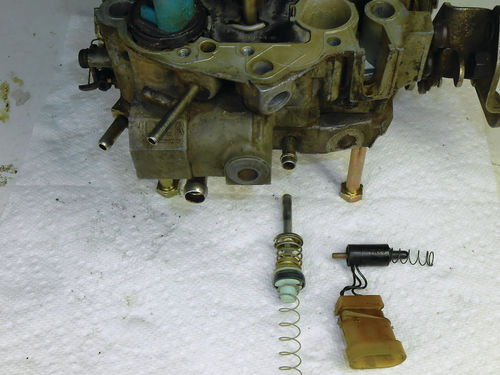
Next Photo 47 shows that the secondary bore air baffle lifts straight up and out. The accelerator pump and return spring, as well as the TPS and its spring can be lifted up and out of their bores as shown in Photo 48.
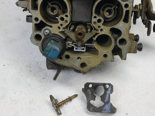
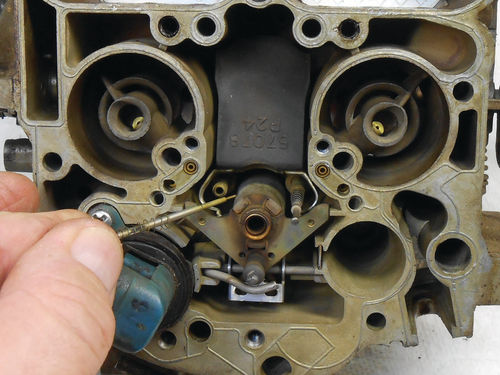
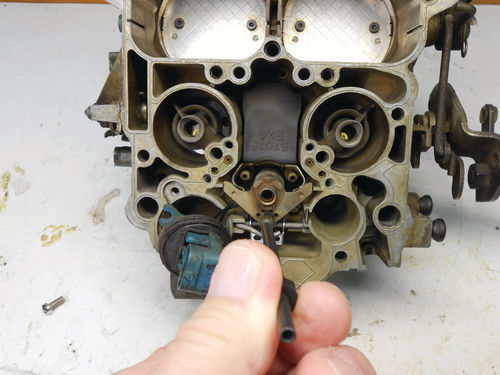
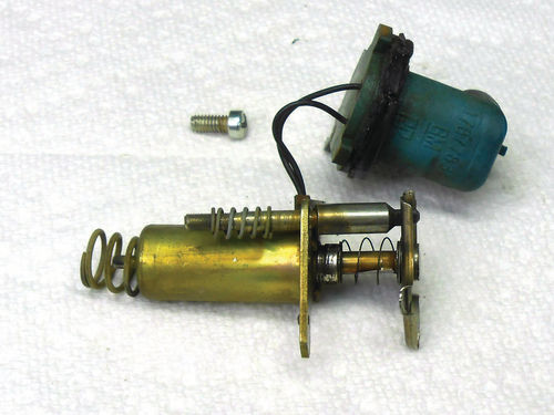
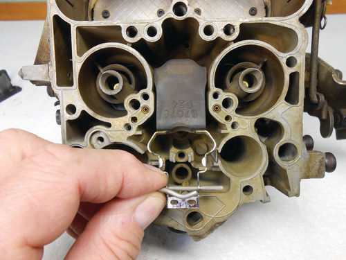
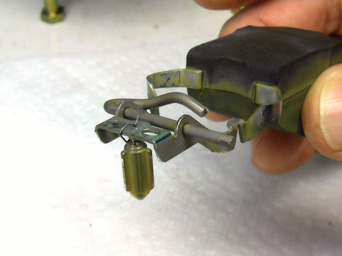
Photo 49 shows both the float bowl insert and mixture control plunger with its spring have been lifted out. Both the primary metering rods are wrapped with a thin return spring and lift out of their guides as shown in Photo 50. While it’s impossible to tell by the photo, the spring on this rod is distorted. It was evident because one metering rod was sitting lower than the other, and confirmed when visually inspecting the spring. A pair of replacement springs will be ordered. In Photo 51 the special tool is being used to remove the lean mixture adjusting screw that holds the mixture control (MC) solenoid in place. Now stop! This is worth noting: After the fact this reference was found. The manual states to make a reference of the lean mixture screw location before removing it. Turn the adjusting screw clockwise until it lightly bottoms while accurately counting the turns necessary. This is a small, fine-thread screw that could easily be damaged, so don’t over-tighten it. Make a written note, and it will be referenced during reassembly. This isn’t a bad idea no matter what. If all else fails you will at least know its original position. Unfortunately, I missed this opportunity. This can also be applied to any of the air/fuel metering devices when encountered. The Phillips screw was removed that secured the electrical connection, and the MC solenoid is free to lift out.
Photo 52 shows the MC solenoid with its plunger and spring installed. That’s the lean mixture adjustment screw and spring riding on the back of the solenoid in the photo. Grabbing the float hinge pin and lifting it out as shown in Photo 53 is all that’s required for removal of the float and needle. Notice in Photo 54 the orientation of the needle pull clip on the float. According to the service manual this is incorrect; the pull clip should be placed on the opposite side (pontoon side). Although there were no problems, it will of course be replaced in the correct location. Evidently this was my error. I had opened the carburetor many years ago and quickly decided to go no further at that time.
Next, we’ll continue with the disassembly.


