OVERHAULING THE LAST OF THE QUADRAJET CARBURETORS PT. 5
Who Would Think That Placing Bushings Would Take This Much Work… Then We’ll Reassemble the Throttle body and Turn to the Fuel Bowl Plugs.
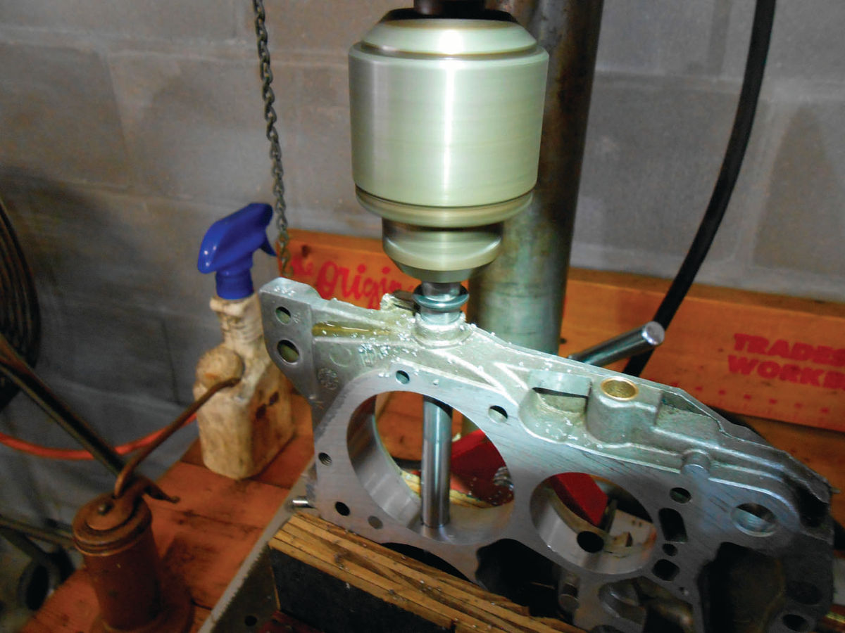
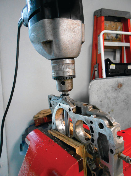
Last month we encountered a problem starting some necessary reaming while trying to install the secondary shaft bushings. So we decided to move from a hand drill to a drill press for this procedure. The fact that there was a drill press available made the decision easy, and no further attempt was made to use the hand drill on this throttle body. With the throttle body secured in the machine’s vise with wood blocks to avoid damage, the cutting commenced as can be seen in Photo 101.
Even in the drill press it required quite a bit of pressure to get the cutting started. Once it started to cut, it proceeded more easily. The rubber O-ring worked perfectly as a stop guide, but it was a different story on the opposite side. There is a tab close to the shaft hole that acts as a secondary throttle shaft stop. Due to the thickness of the O-ring, it wouldn’t clear this tab. Had I thought for a second, it would have been simple enough to reposition the O-ring taking the measurement from the top of this tab, thus stopping when the tab was reached. Well, instead masking tape was quickly substituted as a stop indicator as seen in Photo 102.
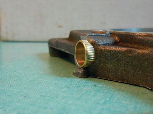
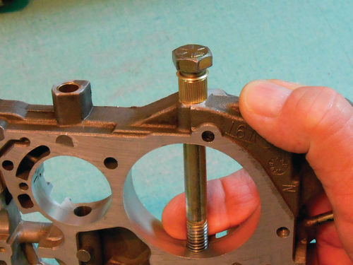
With all the chips cleaned off, the bushings are installed in the same manner; however a 3 ⁄8" bolt 4" in length was used. While one side was no problem, the side with that stop tab once again presented a slight problem as seen in Photo 103. The head of the bolt was unable clear this tab. Photo 104 shows just how much of the bushing remains to be installed. Also notice that the brass bushings that came with this tool have raised ribs around the entire outside perimeter as compared to the smooth bronze bushings used on the primary side (see Photo 91 in Pt. 4 of the series). To allow the bushing to be tapped in the rest of the way, another bushing was slid onto the bolt and used as a sacrificial spacer. Photo 105 shows the bushing has been driven in fully, while the thin top edge of the spacer bushing has rolled over from the tapping. While it will never be used as a shaft bushing; it will be kept as an installation aid and included with the carburetor shaft bushing tools.
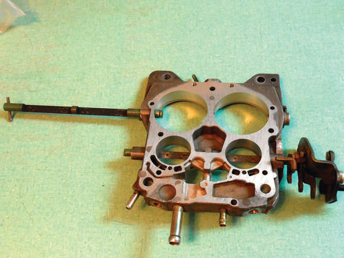


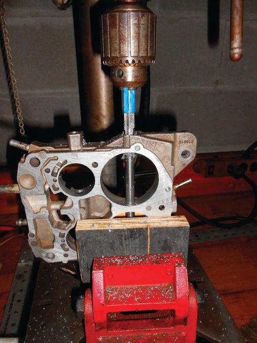
Photo 106 shows that the test fit of the secondary shaft didn’t go quite so well. Testing from either side the shaft would bind, and not pass through. This has nothing to do with the difficulty experienced in getting the ream to cut; the bushings have just closed down once installed. The best solution would be to pass a 3 ⁄8" ream through the bushings and open them up, but when looking through my collection of reams, one couldn’t be found. This is the only practical way to evenly remove the small amount of material needed to allow for the proper fit. The next thought was to apply a small amount of “lay out dye” (used to temporarily color metal), and then move the shaft back and forth to rub off the dye and point out the tight area. It could then be cautiously filed and re-checked until the proper fit was achieved. While not looking forward to this it will work, but by far not the best option and certainly more time consuming. Before getting started, it occurred to me that I had also purchased a similar ream tool from Carb Junky’s years earlier for the 5 ⁄16" primary shaft. It had never been used, and it should be a 3 ⁄8" ream. Well it was and even though the shaft was 1 ⁄16" smaller in diameter than the center hole in the throttle body, it too was installed and used to cut in reverse. The ream’s shaft could be watched as a visual guide in reference to the central throttle shaft hole, as can be seen in Photo 107. The ream was lubricated and then used to make a pass through the bushing. The bushing was cleaned and the shaft tested again until there was a comfortable fit, and then the same repeated for the opposite side. Photo 108 shows both the primary and secondary shafts installed in the throttle body, and almost ready to have their valves aligned and replaced. If I were to do it all over again, I would have separately ordered 3 ⁄8" bronze bushings for the secondary shaft. The 5 ⁄16" bronze bushings have fit perfectly each time they have been used and I imagine the 3 ⁄8" would also. Thinking back to what could have been done differently; only one thing comes to mind. During the initial reaming for the bushing installation, the ream could have been passed in and out a couple more times for each hole. Possibly this might have removed a little more material reducing the pressure on the bushings. On the other hand, the last thing you would want to do is open up the holes too much and then have to deal with loosefitting bushings. As it turned out, all ended up OK.
On To the Other Throttle Body
The swap meet throttle body was not as worn, but also needed to be fit with bushings. The primary side went smoothly and fit perfectly. This time the throttle body was clamped in a bench vise for doing the secondary 3 ⁄8" bushings. Just as before, the end of the ream with the cutting flutes was chucked into the hand drill and set to cut in reverse. It took a ton of pressure, but finally it started to cut.
When the rubber O-ring reached the edge of the throttle body (Photo 109) the pressure was stopped and the ream removed while still under power. When attempting to do the opposite side, it was another story. There was no cutting action. The ream was pulled out, and then pushed back in trying to get it to cut, but the only thing that happened was that the chuck loosened and slid down farther on the ream. Before giving up and going back over to the drill press, I located another 7 ⁄16" ream in my toolbox. It looked essentially the same; however it was probably 30 years older. Why not give it a try? It cut immediately without having to stand on the drill. Wow…even though brand-new the first ream, for whatever reason, was dull.
The bushings were driven in as before and once again the brass bushings had to be reamed for the shaft to fit. If I find myself doing another Quadrajet secondary bushing job, the bronze bushings will unquestionably be used instead. After the experience of using the straight ream I wondered if that Canadian 3 ⁄8" Zako cutting tool could accommodate that stop on the Quadrajet secondary? After an email conversation with the manufacturer and studying the extremely close relationship of the bushing with the stop on the throttle body; there is no doubt to me that the tool stop would need to be almost completely ground off. The other option would be to modify the stop on the throttle body for clearance, but personally I wouldn’t do that.
Putting the Throttle body Back Together
Turning back to the Caprice throttle body, both of the throttle shafts were removed one last time to do a more complete cleaning, paying attention to the recessed areas where the throttle valves attach. The two small primary valves were cleaned with carburetor spray cleaner as well as Acetone, but a few minor stains remained. The shaft was again installed and one of the valves loosely attached using the scribe marks to reference it to the shaft and screw heads. The first valve tends to put up a bit of a fight as there is nothing to stop the shaft from rotating freely, so naturally when trying to get the first screw started the shaft will move.
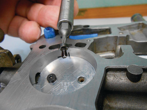
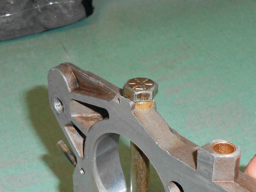
Once aligned, just barely snug the screws and then install the second valve. Once both are in place, check their alignment and how they fit in their bores. They must open and close smoothly with no binding. Hold the throttle body near a light source and closely inspect their fit in each bore. If the scribe marks were correct to begin with, just lining them up should have it extremely close. If all is good, tighten the four screws and recheck it again. If all is still OK, remove one screw and coat it with a permanent thread sealer like Loctite 271 as seen in Photo 110. Now replace and tighten the screw. Once again, make sure nothing has moved and all is properly positioned.
Go over to the other throttle valve and do the same to one of its screws. Loctite 271 doesn’t cure immediately. It states that it sets in 20 minutes and cures completely in 24 hours so there is time to make a correction if needed, but I wouldn’t go and have a cup of coffee.
Now repeat the same process on the two remaining screws. The fact that the screws are being secured with a thread sealant allows you to reuse the old screws if they are still in good condition. With the factory screws you certainly know their origin. Replacement screws that you purchase from outside sources may be fine, but on the other hand who knows where they came from or what standards they may or may not meet.
If you’re reusing the original screws, there will likely be a thread burr on the end of one or two of them. Use a small jeweler’s file or other appropriate tool and carefully smooth off the screw’s end, being careful not to distort the threads. Also remember that the original screws used for the secondary shaft are longer than those in the primary, so don’t accidentally switch them. Just to be on the safe side, the secondary valves won’t be installed until the secondary linkage and springs have all been reconnected.
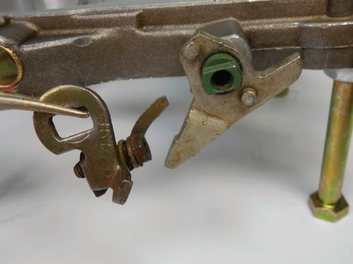
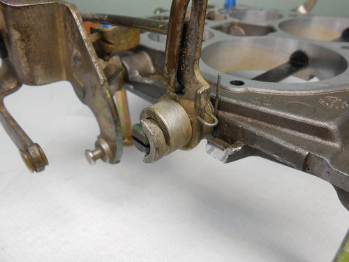
Next the cam follower lever is placed on the primary throttle shaft; the tweezers are holding the fast idle adjustment lever to go on next as seen in Photo 111.
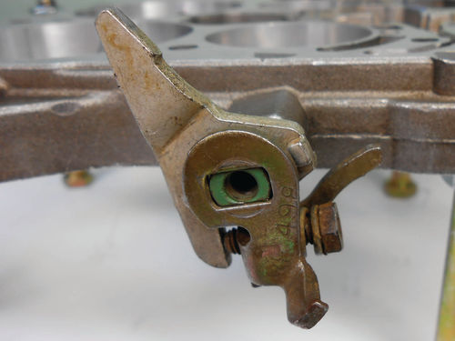
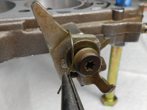
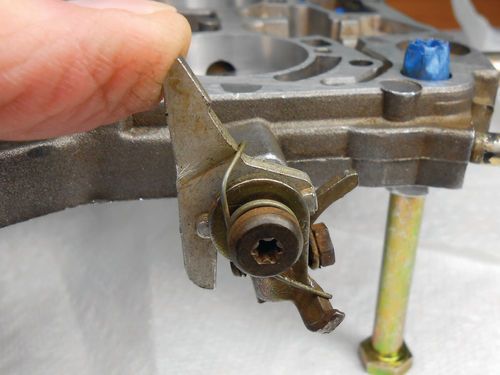

Next, Photo 112 shows the proper orientation of the two levers. The spring and retaining screw are secured, and needle nose pliers are used to hold and load the spring in Photo 113. The cam follower is pushed forward to make sure it moves freely and springs back properly as shown in Photo 114. Now is a good time to install the secondary throttle shaft lever and link as you can see in Photo 115.

Moving on, Photo 116 shows the secondary shaft inserted, but not protruding out on the linkage side, and the spring is set onto the shoulder of the throttle body. Next the lever is lined up with the throttle shaft, and then the shaft is pushed through the rest of the way as shown in Photo 117. Notice also in the photo that the spring is in position to capture the secondary lever, just wind it around ¾ of a turn counterclockwise and up onto that tab to load the spring. A combination of fingers and miniature needle nose pliers seemed to work best for me to perform this task.

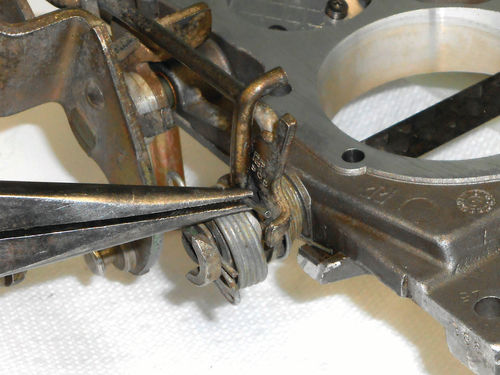
Finally, it’s time to reinstall that hitch pin spring. Because the secondary throttle valves haven’t been installed yet, the shaft has a tendency to want to back out. So the throttle body is stood on end with the opposite end of the shaft being supported on a block of wood, and then the primary throttle shaft is opened fully. This rotates the secondary lever toward the rear allowing for the special spring to be snapped into place as show in Photo 118. Needle nose pliers are then used to guide and load the hitch pin spring by rotating it clockwise until it’s under the ear on the secondary throttle lever as seen in Photo 119.
With the linkage completely reassembled and the function checked, the large secondary valves can now be replaced. The procedure is the same as it was with the primary side. Use the scribed reference marks, visually check the fit of the valves in their bores against a light source, recheck when screws are tightened and verify all is working properly and not binding anywhere. Finally, secure each screw with Loctite 271.

The last thing to do on the throttle body is install the idle mixture screws. The threads are coated with some WD40 and installed using the special double “D” tool as seen in Photo 120. Each mixture screw is brought gently to its seat, and then backed off 2½ turns to its original location
This concludes the service to the throttle body, so it is bagged and set aside for the moment.
Time to Remove and Seal the Fuel Bowl Plugs
The bottom plug repair kit was purchased from cliffshighperformance. com in Mt. Vernon, Ohio (740-397- 2921). It includes the plugs, special epoxy and instructions to do the job.
On the Caprice carburetor there is no question the small plugs are leaking, but what if there is uncertainty? If you see stains or discoloration in the area of the plugs, you can rest assured that fuel has been leaking past them. On the Caprice carburetor the area around these small plugs was definitely stained, however the area around the two large secondary plugs was not. So for sure the smaller plugs must be repaired and resealed, but what about the two large plugs? You might look at them and say if they’ve made it for over 30 years without problems, leave them alone. This follows along the line “if it isn’t broken, don’t fix it.” The other approach is to just do them all and be done with it. After all, you are involved in replacing and resealing the small ones anyway, so why not. At this time I am leaning toward doing the four small plugs and leaving the two large ones alone. Should there become a problem later on, I can look at myself in the mirror and shake my head. Those plugs can be accessed without complete disassembly of the carburetor. It’s mostly a question if the chips created from threading can be successfully removed from the bowl without disassembly.
Next, the swap meet carburetor fuel bowl will be the subject for the first round of plug replacement and resealing.


