Rebuilding SU Carburetors, Pt. 2
SU carburetors have a reputation for being troublesome but they can be kept in good working order with some knowledgeable maintenance and tuning. Last month we disassembled our set of carburetors and assessed the parts. This month we’ll work on their appearance and move on to the reassembly. There were 12 images with the first installment, so we’ll start here with Photo 13.
Cosmetics:
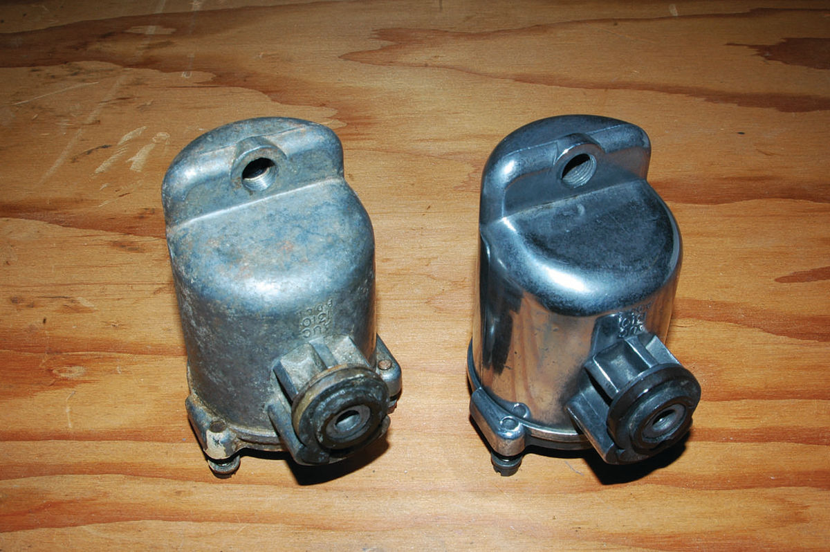
SU carburetor suction chambers and float chambers did not come shiny from the factory in stock applications, but they polish up really well. Highly polished components won’t be concours-correct, but they look great and are easy, though time-consuming, to achieve, so it’s your choice. I went for a moderate polish on the float chamber compared to the unpolished look as shown in Photo 13.
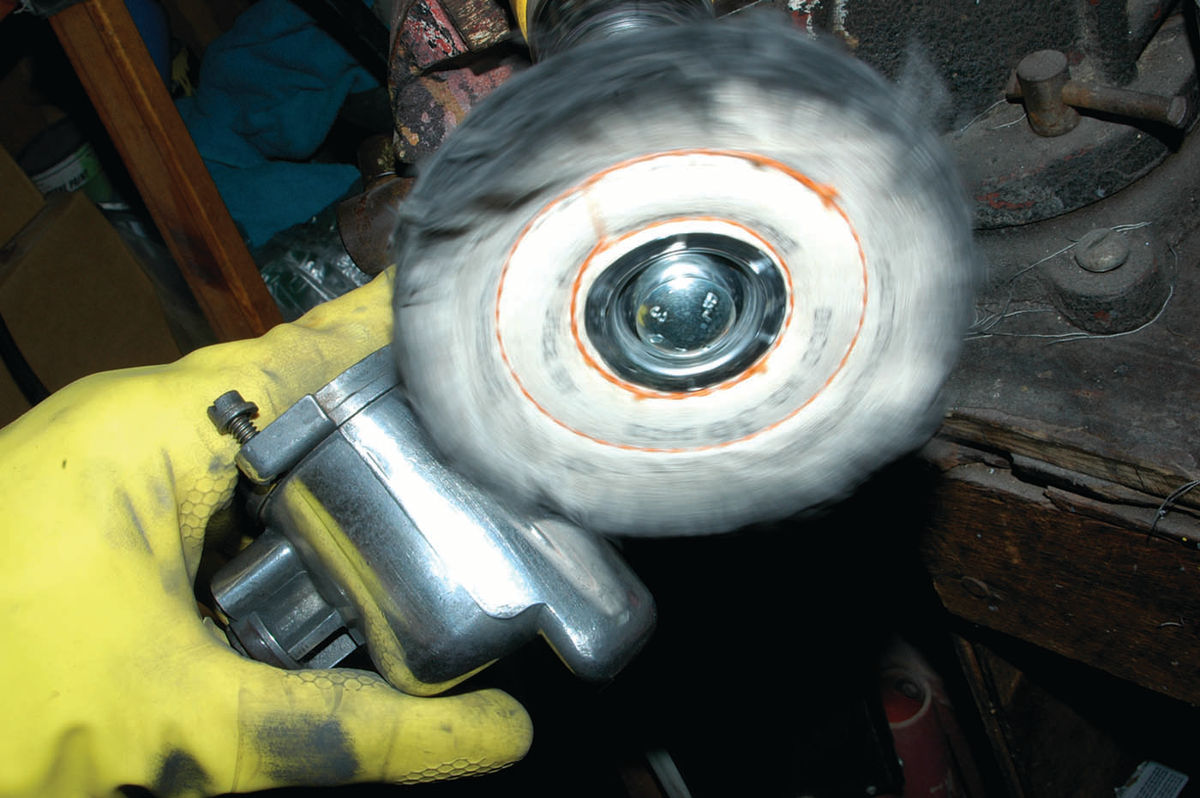
If you choose to polish, you can make the suction chamber and float chamber look great with white jeweler’s rouge and buffing wheels. I used gray and blue Dico Nyalox fiber wheels for initial cleanup and then Dico cloth buffing wheels (Pictured Below) and white jeweler’s rouge from ACE hardware.
If you want to go for an even higher level of polish, you can use red rouge and the appropriate cloth buffing wheel recommended on the rouge packaging. But before you take that approach, give some thought to what would be the overall assembled appearance.
If you highly polish the suction chambers and float chambers and leave the carburetor body and linkages untouched, the contrast will just tend to make the unpolished parts looks bad. You will have to at least clean up the main linkage rods, levers and carburetor body to a nice satin appearance with a fiber wheel or other means. Bead- or walnut shell media- blasting are ideal if you have access to this kind of equipment. Electroplating of screws, nuts, linkages, etc., (Eastwood has a kit for $70) is also an option if you want to go to the time and expense.
Reassembly
At this point, you should have examined and cleaned everything and have on hand new parts that are needed as project replacements.
Throttle shaft and disc: If you are replacing the throttle shaft, you now need to completely take apart the throttle shaft assembly which includes the throttle shaft, the throttle return lever, the lost motion lever, the tab washer and the nut (Photo 15, below).
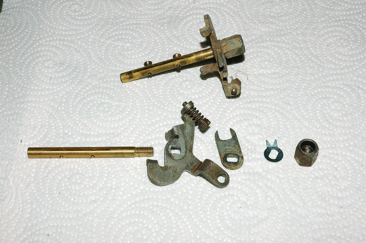
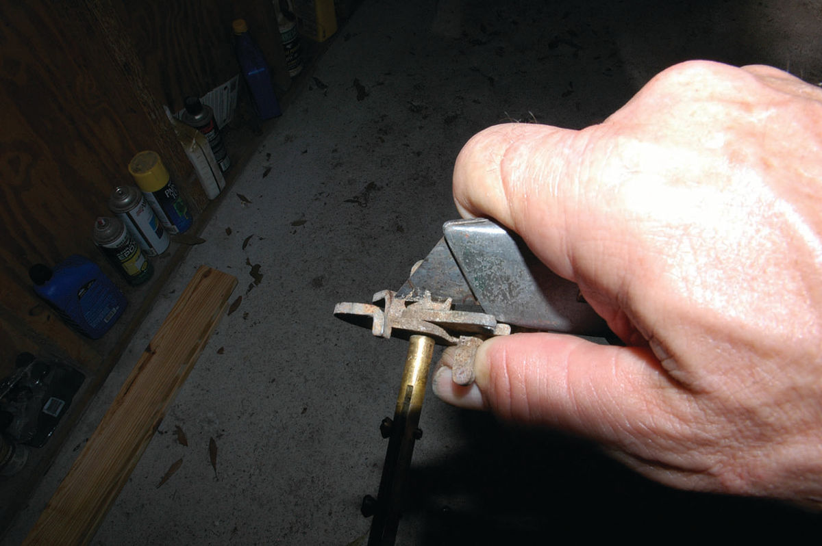
While doing this you should be making notes and taking photos or otherwise ensuring you will be able to assemble the parts in the proper order and orientation. Pay special attention to the orientation of the throttle disc screw holes in the throttle shaft; they are larger and funnel-shaped on one side to accommodate the screw heads, and this determines the orientation of the chamfered throttle disc, which fits only one way. The two carburetors in a dual setup are mostly mirror (opposite) images, so you can use the throttle shaft from the other carburetor for reference-only with that in mind. Before you can unscrew the nut holding the throttle shaft assembly together, you’ll need to bend down the ears on the old tab washer (Photo Below).
Reassemble the shaft assembly with the new shaft, remembering to bend up the ears on the tab washer, then slide the shaft into the carburetor and insert the throttle disc. Make sure you insert it the correct way, so the beveled edges lie flat against the venturi walls top and bottom. Unless you are just lucky on the first try, this may seem impossible, as it is a very tight fit. But there is a throttle shaft position in which the disc will slide easily into place. Real SU aficionados may know a trick for this procedure, but trial and error is the only one that worked for me.
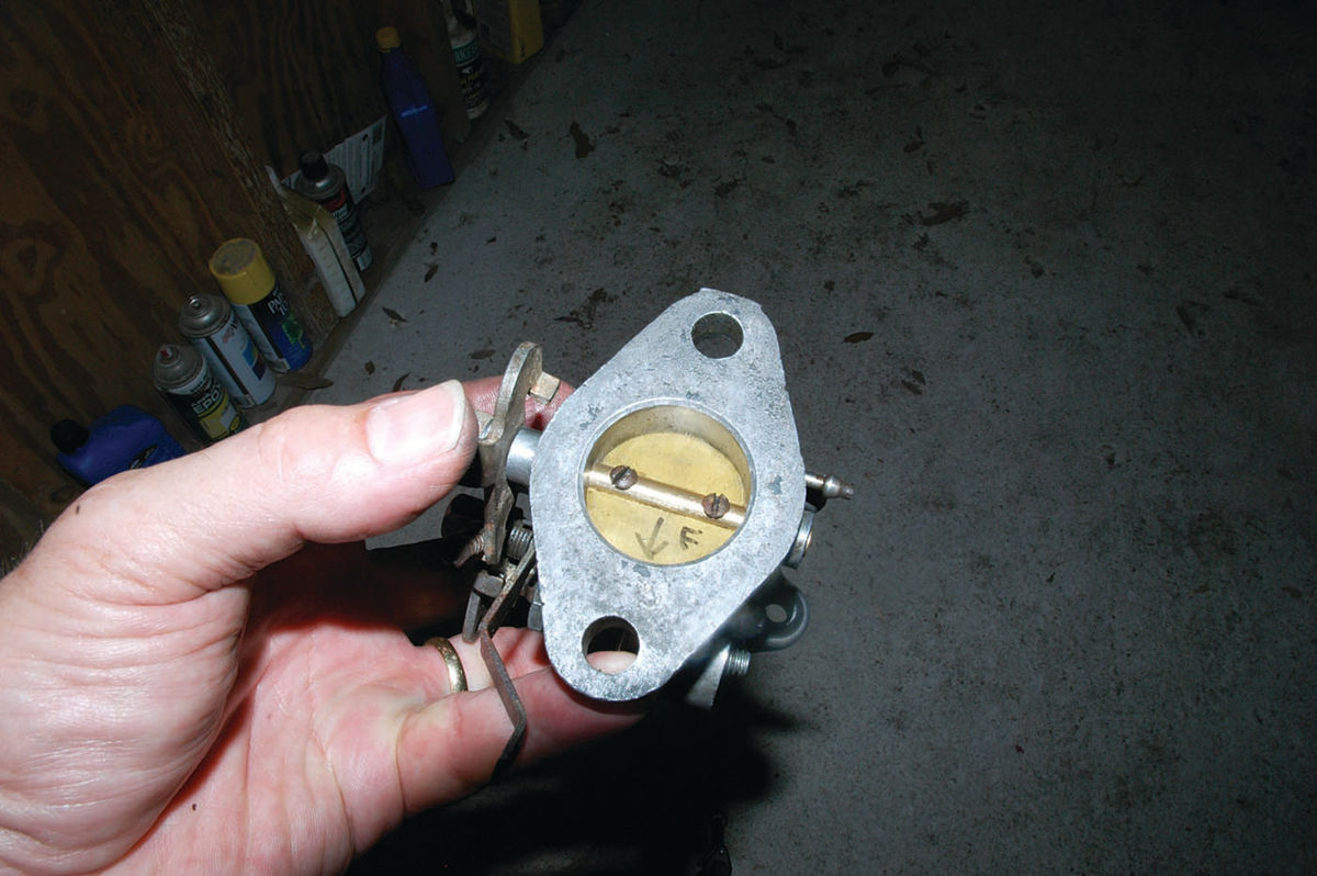
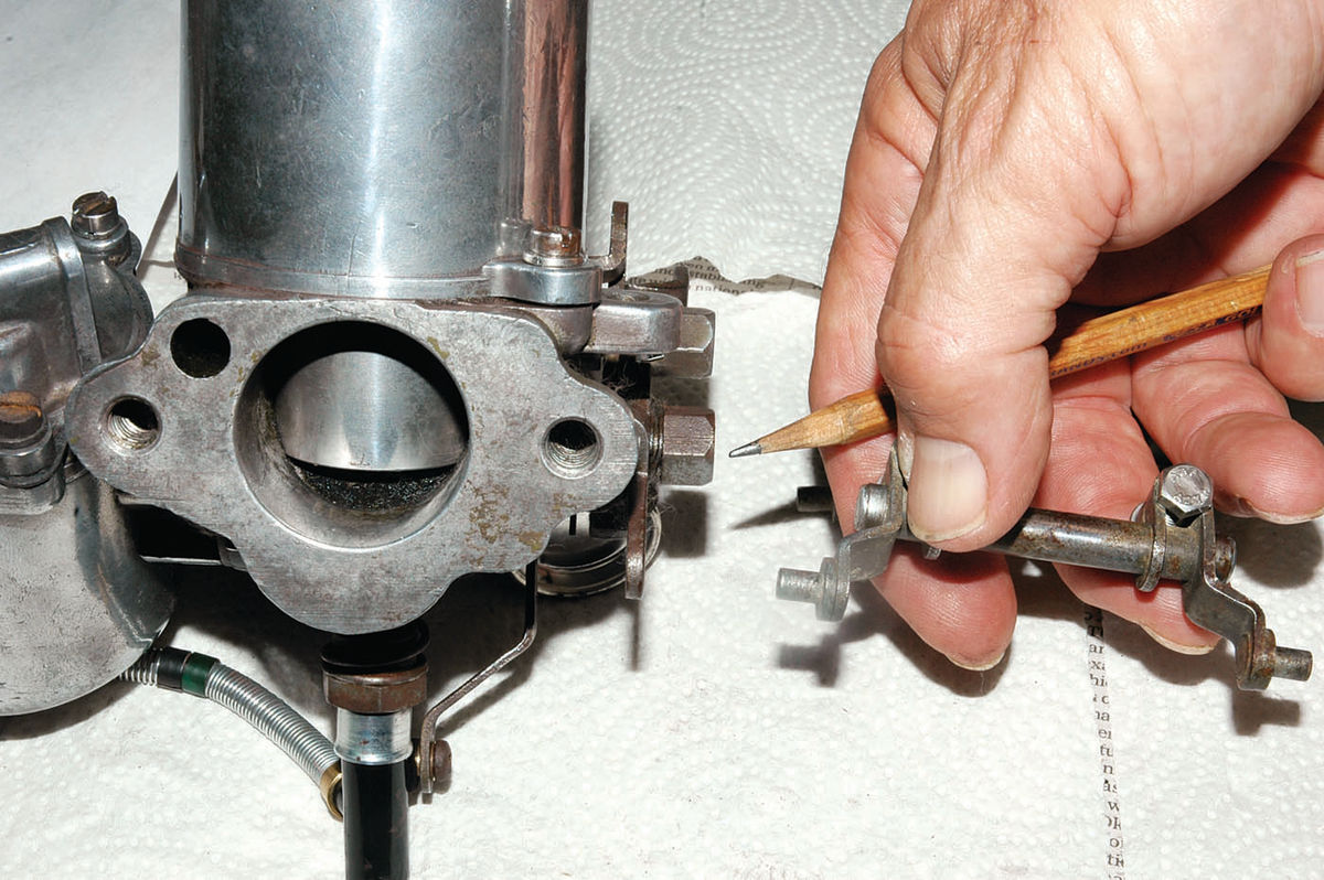
Once you have the throttle disc in place and the screw holes in the disc lined up with the screw holes in the shaft, insert the screws, tightening them only slightly. Then carefully move the throttle shaft to close the disc; wiggle the disc around as necessary until it closes completely and tightly in the venturi. Check this fit with a light shining from the back side. Take your time and get this right before tightening the screws and then spreading the split ends from the back to lock them in place. I marked the disc (Photo Below) on this carburetor with an arrow for the bottom and F for front carburetor when I removed it.
Float Chamber Assembly
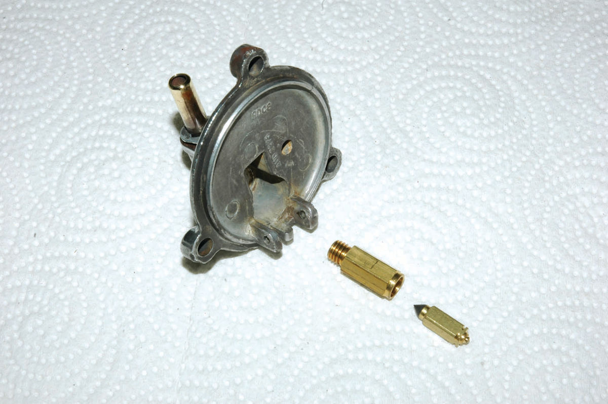
Examine the float chamber lid, remove the old float needle, and unscrew the float needle seat. Assuming the lid and its passages are nice and clean, install the needle seat and the needle (Photo Below).
Be careful that the float needle doesn’t fall out, as the float is what holds it in place. Next hold the float in place with its hinge opening between the hinge brackets on the float lid and insert the hinge pin as was shown in Photo 8. (Note, all photos below #13 were with last month’s installment.) This pin is a slip-fit held in place by friction and secured on either end by the float chamber body on reassembly, so make sure the pin doesn’t fall out during the next step. Invert the float lid and float assembly, and eye- ball the space between the float and the float chamber lid. This gap should be no less than 1/8 (one-eighth) inch and no more than 3/16 (three-sixteenths) of an inch. Check this with a drill bit or other spacer of the correct size. If the gap is outside these parameters, carefully bend the float hinge so the gap is correct, being careful to not disturb the part of the hinge that contacts the needle valve or its attachment to the float. Install the float lid and float assembly on the float chamber with a new gasket, ensuring that the brass float securing pin is still properly centered on the lid hinge bracket and that the fuel inlet tube is properly oriented to the carburetor body. Three screws with spring washers hold the lid in place. Don’t forget that ID tag, which should be underneath the outboard screw (Photo Below).

Next, secure the assembled float chamber to the carburetor body, ensuring that the large rubber grommet with its metal support washer underneath are properly seated in both components. The large rubber grommet has a slot in it that properly positions the float chamber in relation to the carburetor body. The bolt that passes through the carburetor body and secures the float chamber should have a metal flat washer on the head side and a new rubber washer (provided in a rebuild kit) on the float chamber side.
Jet Needle and Piston
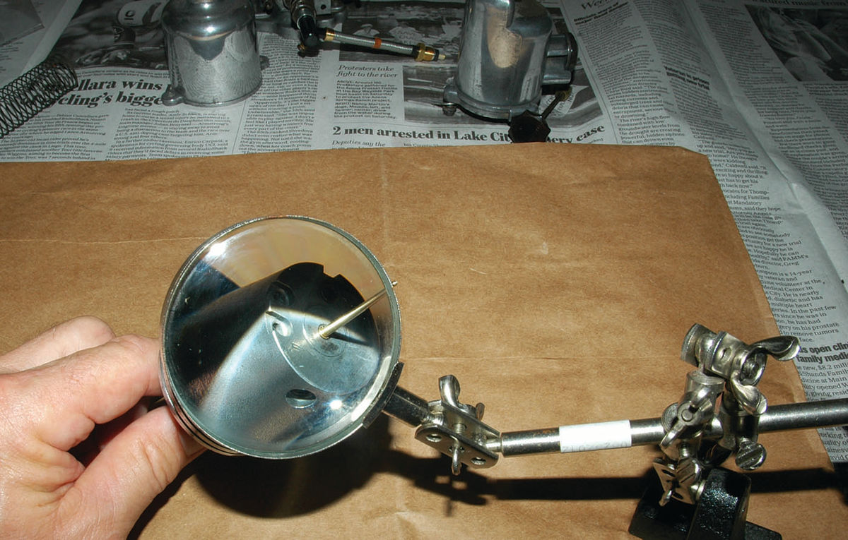
Install the new jet needle in the suction chamber piston. Make sure the flat shoulder at the base of the needle is flush with the surface of the piston (Photo Below). The needle hole in the bottom of the piston may require some cleaning for the new needle to easily slide in place. You shouldn’t have to force the needle or you risk bending or otherwise damaging it.
Tighten the set screw that secures the needle and set the piston aside with the suction chamber and spring.
The Jet Assembly
Jet assembly is fairly straightforward but does necessitate a somewhat tedious procedure to center the jet properly in relation to the jet needle that sticks down from the bottom of the suction chamber piston. This is what worked for me. Lay the jet assembly parts out in order. From bottom up they are the new jet and its feeder tube, the jet adjusting nut, the adjusting spring, the jet securing nut, a metal washer and the jet bearing tube.
Insert the jet bearing into the carburetor body, then the metal washer, and then loosely tighten the jet locking nut around the bearing. Screw the adjusting nut onto the threads of the jet bearing tube without the adjusting spring and screw it all the way up. Slide the jet assembly as far as it will go into the bearing tube. Determine that the jet locking nut next to the carburetor body is just loose enough so you can easily rotate the jet bearing with your fingers. Now install the suction chamber/spring/pis- ton assembly onto the carburetor body (see Photo 4), carefully aligning the key in the carburetor body with a keyway on the piston and easing the jet needle into the jet. Don’t force anything; it should easily slide together. Now tighten the two screws holding the suction chamber in place.
Raise the piston with your finger to its highest position and let it fall. The piston should move easily and hit the jet bridge with a soft but distinct click. If it doesn’t go all the way down, make sure that the jet securing nut is a bit loose, that the jet bearing tube is loose enough to rotate and that the jet and its feeder tube are roughly in the position they will be when attached to the float chamber. Unscrew the damper from the top of the suction chamber, and gently push the piston down with a wooden dowel or the eraser end of a pencil until it contacts the jet bridge. This should center the jet, which can move slightly in relation to the jet metering needle.
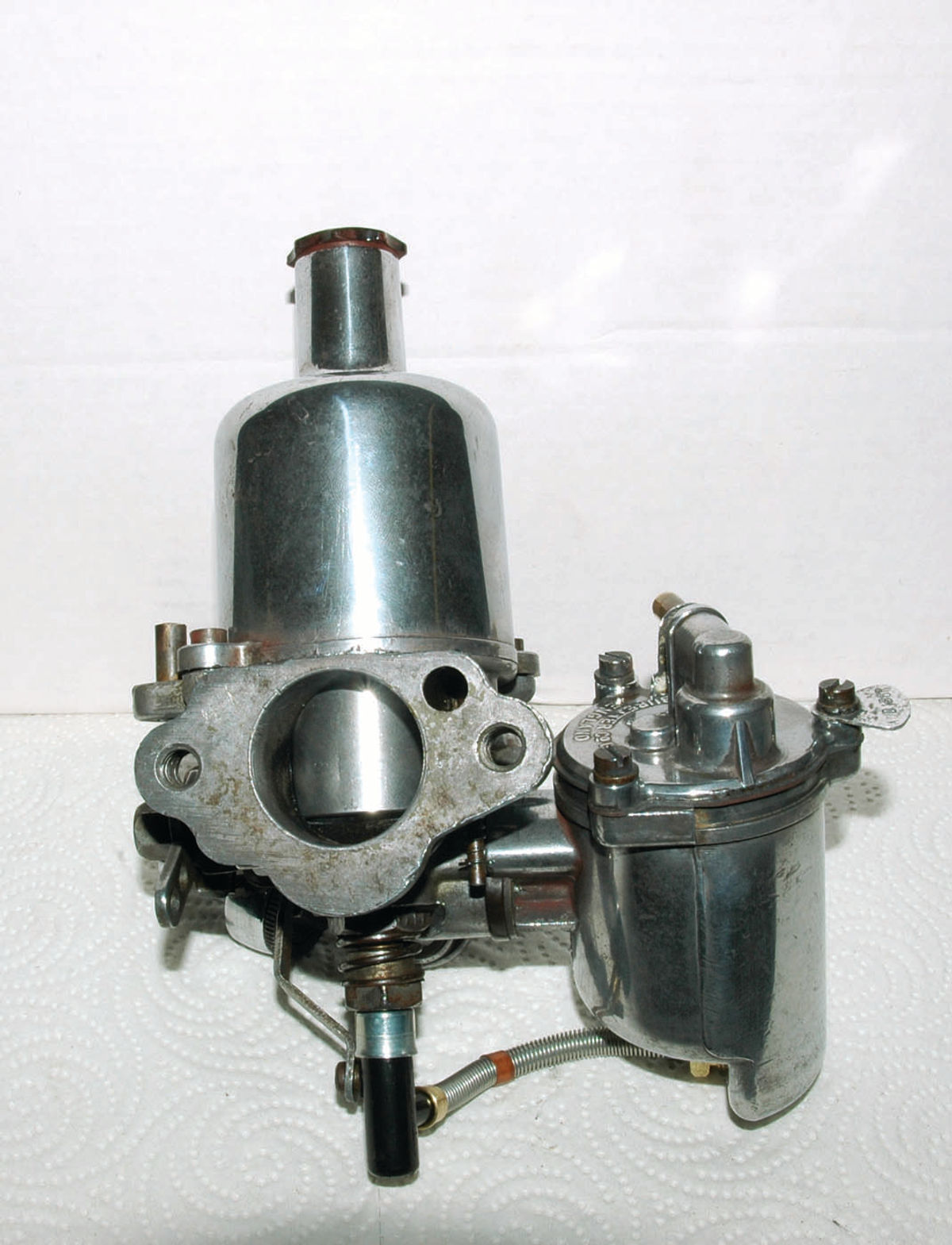
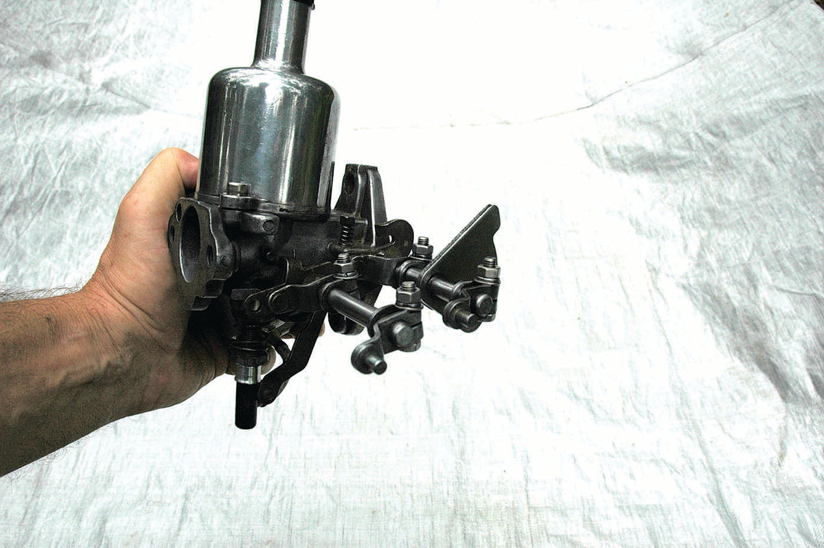
Lift the piston again and observe that it moves freely and hits the jet bridge with that soft click. If it does, tighten the jet locking nut, loosen the jet adjusting nut, move the jet out of its bearing about half an inch, and go through the lift and drop procedure again. If the piston still falls freely and you hear the same soft click, you’ve successfully centered the jet. If not, loosen the jet locking nut again and repeat the procedure until the piston falls freely and the sound is the same at the top and bottom of the jet adjustment range. Then retighten the jet locking nut, unscrew the jet adjusting nut, install the jet adjusting spring and replace the adjusting nut. Once you are satisfied with the jet centering/assembly operation, attach the jet link that is still on the side of your carburetor body to the jet head with the small screw and bushing (Photo 5). Attach the new jet to the outlet at the bottom of the float chamber, making sure the components on the end of the wire- wrapped, jet feeder tube are in the correct order (Photo 11). From the jet-head side, the order is; the wire wrapped plastic tube, threaded nut, small metal washer and small rubber grommet that holds everything together and seals the joint with the float chamber. Make sure the plastic tube protrudes about 3/16 of an inch beyond the rubber grommet at the end of the assembly for a good seal. You are now done with one carburetor, and it should look similar to this (Photo Below), depending on model.
Regardless of the number of carburetors, when you are done rebuilding, the next step is putting it all together with linkages, heat shield and intake.
Final Assembly
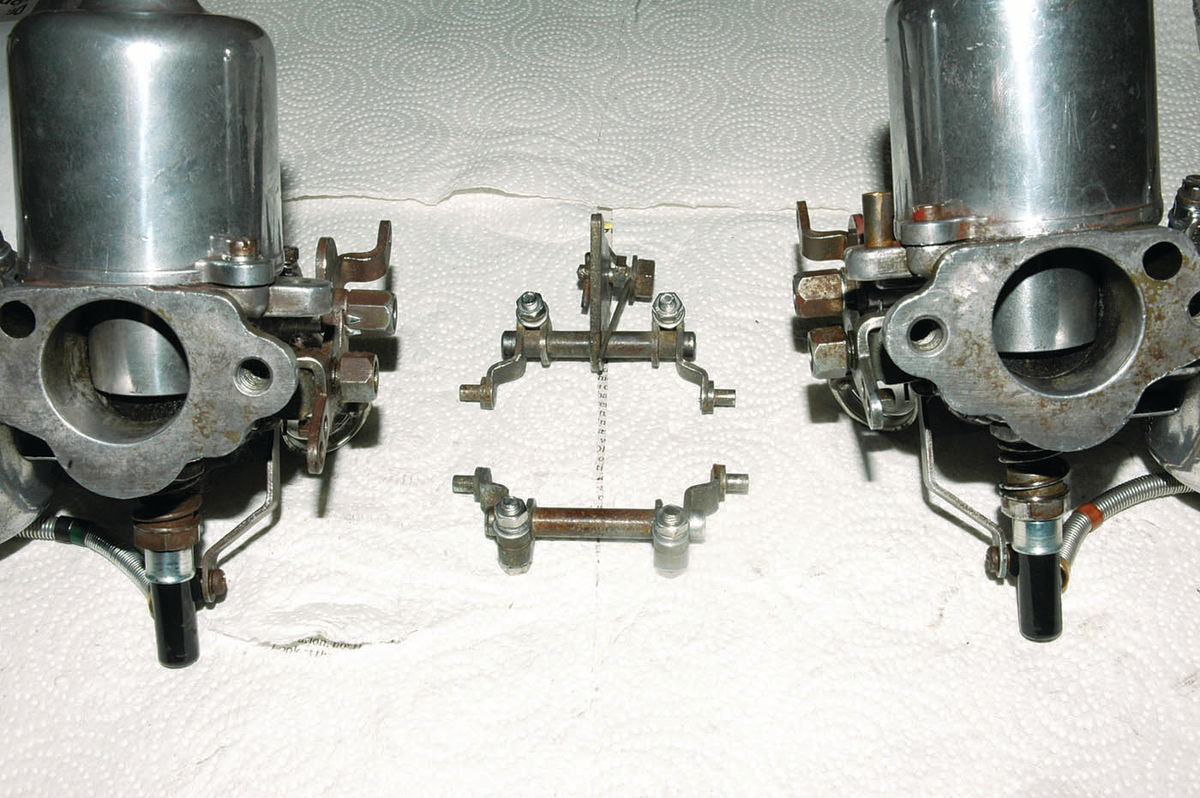
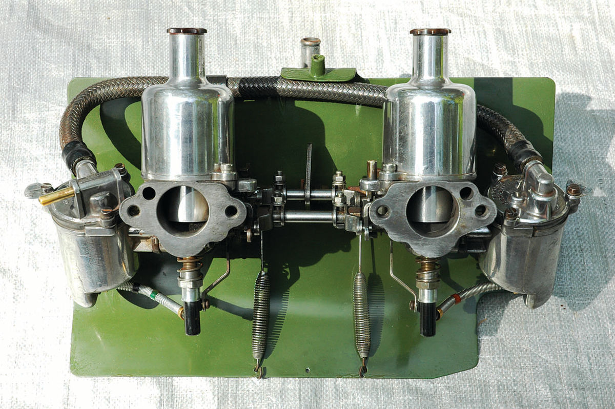
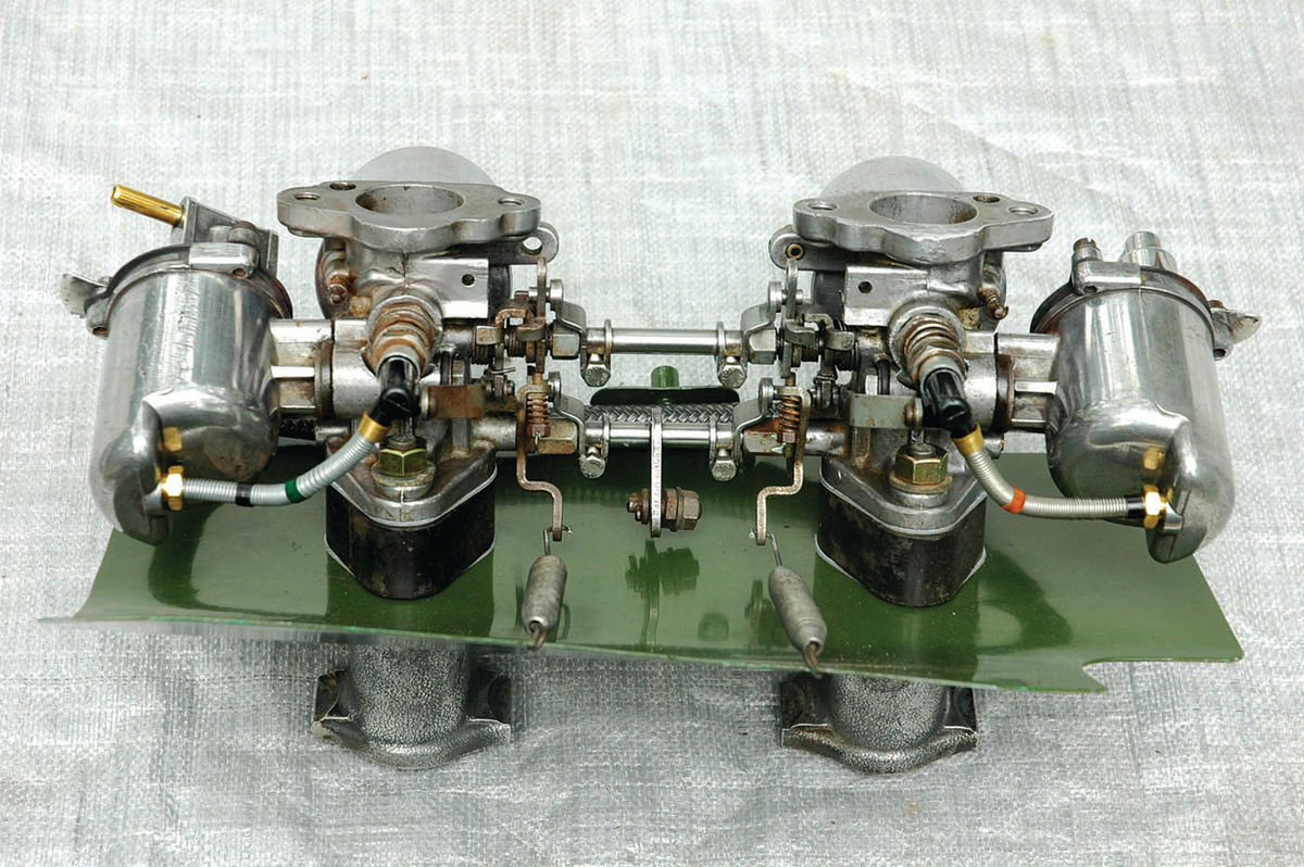
Lay the finished carburetors out in proper position front and rear with the connecting linkage between them (Photo below).
Insert the throttle operating rod and jet operating rod ends into the open- head nuts on one carburetor (Photo Below), making sure the pins on the throttle and jet operating levers are properly inserted into the appropriate hole or slot on the levers attached to the carburetors.
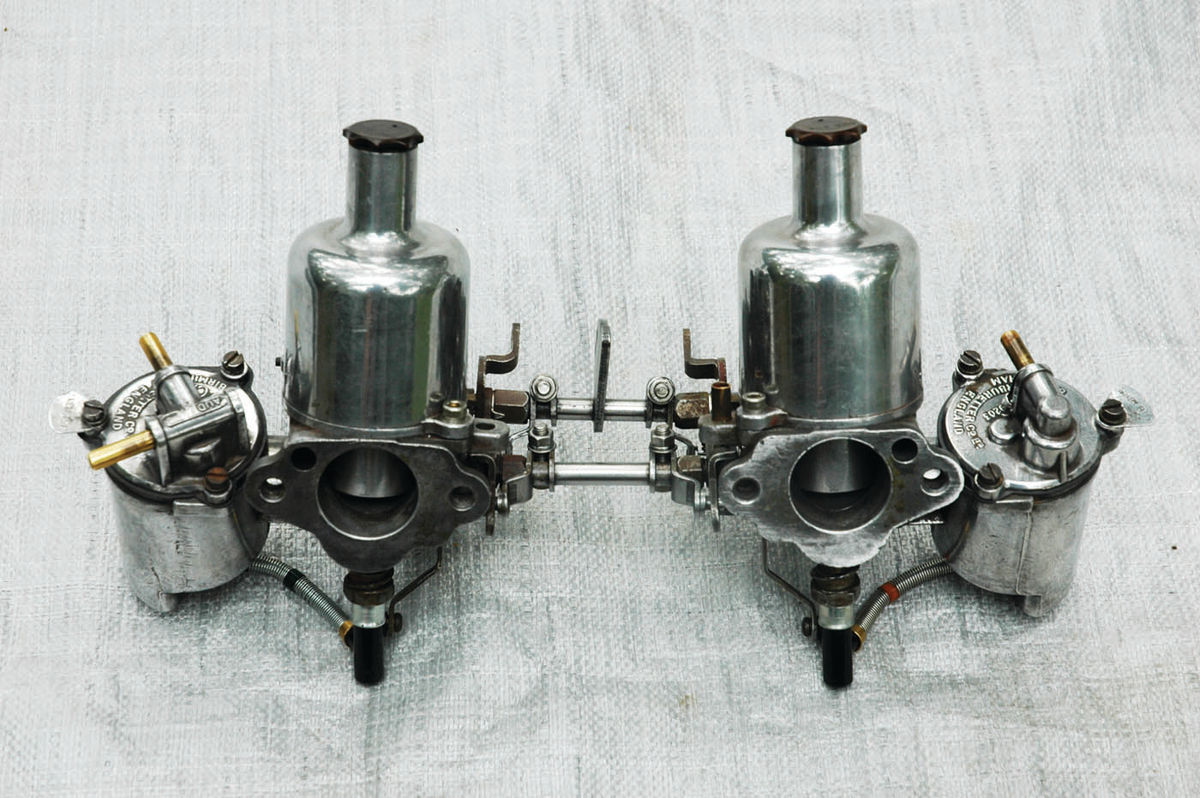
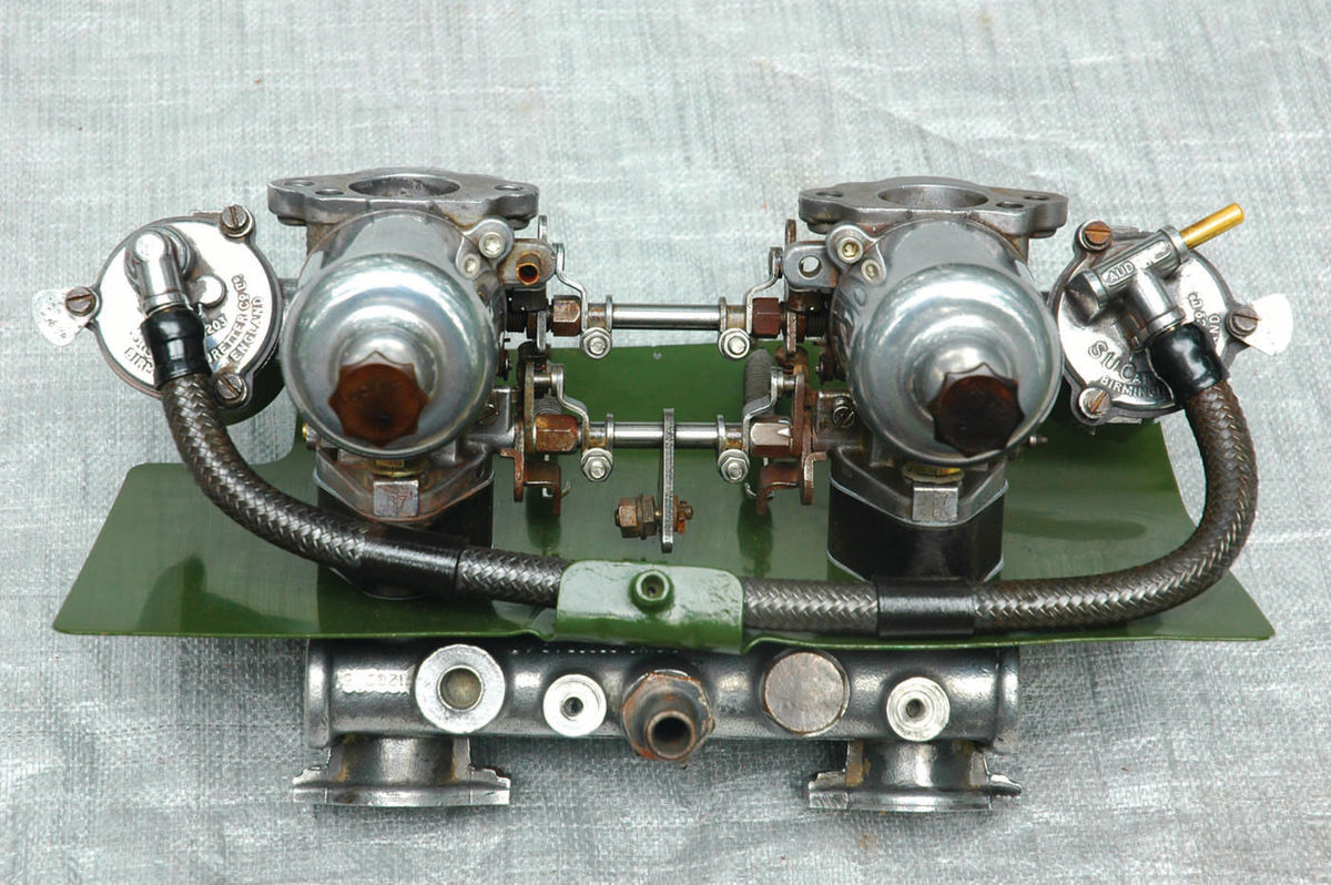
With both rods in place on one carburetor (Photo Above), bring the two carburetors and the linkage together, inserting the rod ends and lever pins into the appropriate holes and slots on the other carburetor levers (Photo below).
Once you have inserted the linkage between the carburetors, set them care- fully aside while you prepare the heat shield, intake manifold, spacers and gas-kets in the proper order. Assembly order, from the manifold side, is; manifold, gasket, heat shield, gasket, hard rubber spacer, gasket, carburetor.
The installation of the original, braided fuel connector line and throttle springs completes this rebuild.
The finished product will look some- thing like this, depending on your model.
Before performing the installation on your car, remember to add the correct amount of light engine oil to the damper chamber (under the screw-cap on top of the suction chamber). The shop manuals and other resources listed below will be useful for adjustments and tuning particular to a given application.
Time Involved
This rebuild took me about 35 hours total and included polishing many components and restoring the heat shield (welding a stress crack, grinding, prim- ing, sanding and painting in Austin- Healey Sprite engine green). The time also included taking photos for this article, so it might take you less time


