
Rebuilding SU Carburetors, Pt. 1
They’re In Wide Use but Have a Reputation for Being Difficult. This Will Help Keep Them In Good Working Order.
FOR DECADES SU carburetors have fueled a wide range of British vehicles including MG, Austin-Healey, Jaguar and even Rolls-Royce. Volvos, Saabs and early Datsun Z cars (with a Japanese-built version) also were fed by SUs. Variants—and sometimes hometuned adaptations—have been used on Harley-Davidson motorcycles as well.
SU carburetors look and operate differently from the Holley and Rochester carburetors Americans are commonly familiar with and they sometimes are misunderstood and discarded as being unreliable or too difficult to keep in tune. But in reality they are simple, reliable and very durable, given some knowledgeable maintenance and tuning.
Burlen Fuel Systems Ltd. now produces new units as the SU Carburetter [CQ] Co., but a set like those featured here, the HS2 model AUD136 that was stock on the early- to mid-’60s Austin Healey Sprite, MG Midget and Mini Cooper S, will run $800 or more from Moss Motors, Victoria British Ltd. or Seven Enterprises Ltd.
Rebuilding an original set is a very practical and satisfying option—even a novice can do it—and it helps to preserve the originality of your car.Virtually all parts are available, but expense can add up quickly if you need more than a basic rebuild kit,so it’s wise to first disassemble the carburetor and evaluate very carefully whether it makes sense to rebuild or buy a used rebuilt or new set.

Taking It Apart
Different models of SU carburetors will differ in detail and size, so some of the images shown here may not look exactly like your carburetor, but the basic procedures on most versions will be similar. Many models, like the H1 dual carburetor setup on the Mk1 Bugeye Sprite or the HD 8 triple-carburetor setup on the Jaguar XK-E have different jet and float arrangements. Obviously,triple-carburetor installations, like those on the big Austin-Healeys or Jaguars, will be more complex in their final assembly on the car. There are many fine books and online sources that can help with information about carburetors that differ from those featured here.
Disassembly of an SU carburetor is pretty straightforward, but there are some potentially troublesome spots in the process.
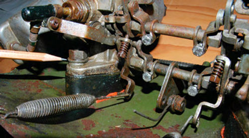
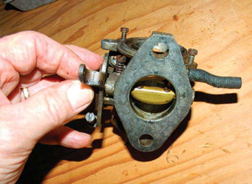
Keep in mind that if this is new territory for you, careful photo documentation from all angles before you start taking things apart is very helpful. Think about what images would be helpful when trying to put this thing back together six months from now when you’ve forgotten all the little details. This is how my carburetors looked in the beginning (Photo 1), very complete and original but with virtually every moveable part seized up from decades of storage.

Note the small metal tags on either side at the top of the float chamber (Photo 2). These are the primary model numbers on the carburetors. They allow you to determine roughly what year vehicle they came on, and they are also very helpful in ordering parts. Unfortunately, these tags are frequently missing if the carburetors have been worked on previously. Fortunately, the major components also have numbers of their own, so all is not lostifthe main tags are missing.
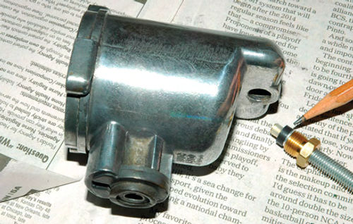
Remove the four hex nuts that hold the carburetors to the intake manifold and heat shield. Note the position of the thick, hard rubber spacers and gaskets. The hex nuts are a close fit between the carburetor suction chamber (the bell shaped piece) and the intake mounting bracket on the carburetor body (Photo 3).
The linkage between the two carburetors in a twin setup looks complicated but really isn’t. As you remove the carburetors from the intake, the jet rod (in front) and throttle rod (in back) will slide out of a slip-fit nut along with their operating lever assemblies.
Have three boxes ready as you take the carburetors apart—one for the front carburetor, one for the rear, and one for the parts they share. It is very important not to mix up the parts from a multiple carburetor set.
Once the carburetors are removed from the intake/heat shield and the connecting linkage between the two has been removed and set aside, disassemble the carburetors one at a time.
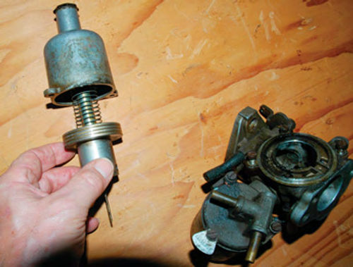
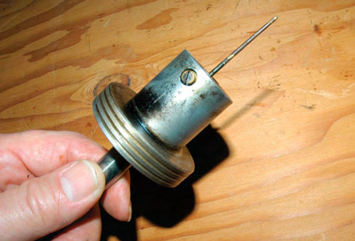
Remove the two screws that hold the suction chamber in place. This will allow you to remove the spring, piston and jet needle assembly (Photo 4).

Unscrew the hex nut that holds the flexible, wire-wrapped jet feeder tube to the float chamber and remove the Philip’s screw holding the jet link to the jet rod mechanism on the side of the carburetor (Photo 5). Be careful not to lose the tiny bushing that positions the screw in the jet link.
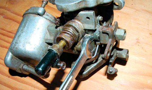
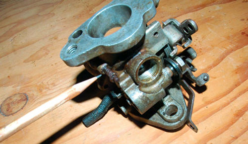
Now you can remove the hex bolt that passes through the carburetor body and secures the float chamber. You might have to shift the spring-loaded jet lever on the side of the carburetor body to access this bolt (Photo 6). As you remove the float chamber from the carburetor body, a rubber grommet and washer assembly might remain in the carburetor body, or it might come out with the float chamber. You want to preserve this assembly if possible. The grommet has a slot in it that properly positions the float chamber, and this is not a part that normally comes in rebuild kits.
Next, loosen the adjusting nut (bottom one) on the jet assembly, along with the jet securing nut closest to the carburetor body, and remove the whole jet assembly (Photo 7).
Remove the three screws holding the float chamber lid and the float in place, being careful not to lose the ID tag. The float is secured to the float chamber lid with a tiny slip-fit brass pin (Photo 8). I had to soak mine in WD-40 overnight and still had to drive it out with a punch. If yours is similarly reluctant to budge, apply force very carefully so as not to damage the float, float hinge or float chamber lid.
Now, examine the carburetor body that still has the throttle disc and throttle shaft in place. Grab the throttle shaft return lever and try to wiggle the throttle shaft perpendicular to its bore (Photo 9). If you can feel movement, the shaft will need to be replaced, at the very least.
Also, hold the carburetor body up to a light from the back side of the throttle disc. When it is closed you should not see light around the edges.
Remove the two small screws holding the throttle disc in place, and carefully slide it out of the throttle shaft and carburetor body. This is a very tight fit, and you may need to move the shaft with the throttle return lever to discover the one place where the disc will slip out. Examine the disc carefully as it comes out. It is beveled top and bottom and only fits in one way. It is a good idea to mark the top or bottom to indicate orientation.
When the throttle disc is removed, again try to wiggle the shaft in its bore. If you can’t feel any wiggle, slide the shaft out of its bore with its attached throttle return lever assembly in place, and eyeball the shaft carefully. If There is no movement and no visible wear, you won’t need to replace the shaft, but it’s pretty rare to be so fortunate, and it makes sense in most cases to go ahead and replace the shaft while the carburetor is apart. If there is only very slight wear at either end of the shaft, a new shaft should solve the problem. If wear is more significant, there are two options; replace with an oversize shaft, or re-bush the carburetor body. Re-bushing is probably the best option. The shaft fit is something that has to be right for the carburetor to work properly; otherwise air will leak and it will be difficult or impossible to tune.
Neglected throttle shafts are one of the most common sources of problems with SU carburetors. Local British car tuning shops should be able to help with assessing the state of the throttle shaft/bore and re-bushing the body if necessary. Or, there are internet-based businesses— such as BritishClassicMotors.com—to which you can send your carburetor body forfitting bushings, a throttle shaft, etc.
At this point, disassembly is basically complete. The levers and spring assemblies on the side of the carburetor body can remain in place unless there is an obvious problem. I have left the description of the final disassembly phase of some small sub-assemblies for the assembly section to avoid confusion and having too many tiny parts lying around. If you have a multi-carburetor setup, once all are apart (and carefully separated) you can proceed with assessment of parts that might need attention.
Assessing the Components
Typical rebuild kits are likely to include gaskets and washers, the float needle and seat, and the jet assembly. They do not include the jet metering needle, floats, throttle discs or throttle shafts, all items you might need to replace.
The jet metering needle is a good place to start. Loosen the set screw that secures it and remove it from the suction chamber piston (Photo 10). Examine it visually and by feel. A magnifying glass is a big help. Any corrosion, pitting or wear ridges dictate replacement. If in doubt, replace. On the base of the needle is (depending on carburetor model) a one-to-three place alpha-numeric code indicating standard, rich or weak mixture. You will need this number when ordering replacements.
Next, examine the float for any obvious signs of damage or leaks. Shake it and listen for fuel inside. Immerse the float in water for several minutes and watch carefully for bubbles. If there are no leaks or other signs of damage, you can reuse the float.
Examine the float chamber itself. Make sure the complex structure in the bottom is clean and free of deposits. A sharp pointed hardwood dowel is a good tool for scraping away deposits. Solvent Soaked Q-tips are also useful, though make sure you don’t leave any cotton bits inside the outlet to the float tube. Also, examine this outlet carefully from the outside to make sure the small rubber grommet on the end of the float tube (shown in Photo 11 on the new jet assembly) didn’t remain in the outlet when you unscrewed the old jet assembly from the float chamber.If it did, you won’t be able to screw the jet tube into the float chamber. Two of these rubber grommets won’t fit. I speak from experience.
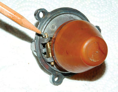
Next, find the small,spring-loaded piston-lifting pin on the underside of the carburetor body (Photo 12). You should be able to easily push this up and have it spring back into place.
On my carburetors, these pins were a good example of those maddening little unexpected problems that can eat up so much time. I had to soak them repeatedly in WD-40 and, in the end, apply way more force than I was comfortable with to free them up.
Examine the jet assembly and its related parts as they came out of the bottom of the carburetor body. There are six separate pieces to this structure on the HS2 carburetors. From the bottom up, these are the jet and its feeder tube, the adjusting nut, the adjusting spring, the jet securing nut, a metal washer and the jet bearing tube. The jet should have easily slid out of the bearing tube when you unscrewed the whole assembly from the carburetor body. If not—time for more WD-40. You will need to reuse the bearing tube, plus the adjustment and jet securing nuts. A new jet will come with a rebuild kit.
By now, you should know what parts you will need to order in addition to the standard rebuild kit. You are likely to have some time on your hands while waiting for the new parts to arrive, so this is a good time to consider carburetor appearance.
Next, we’ll work on the carburetors to make them look better and then get on with the reassembly.


