Make & Install a Custom Headliner
With Many Cars You Order a Headliner and Then Put It in Place, But Project ’46 Required a Special Approach.
BEFORE ANY OF the previously constructed trim panels can be mounted in the car, I need to install the headliner.
The important thing to understand here is that the headliner that is going into the ’46 Ford is custom-made. It isn’t like the headliner in your Toyota; it doesn’t fall down after removing a few screws. Once installed, it is in the car forever. That means any wiring for a dome light or sail panel speakers must be done beforehand.
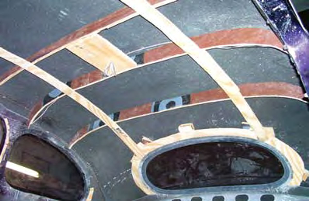
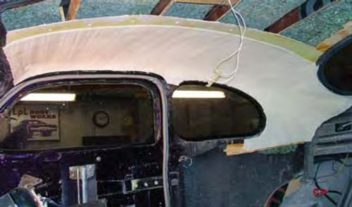
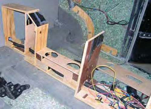
Take a look at Photo 1. This is the completed framework for the new headliner. Eventually this framework will be covered with cardboard, foam and vinyl material to form the new headliner. Notice that the wires for the dome light have already been added.
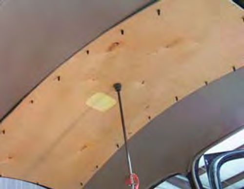
To make this framework, I start by cutting new headliner bows (Photo 2). These are cut from 1/2-inch-thick plywood, and will stand vertically in the car. I’ll make them about two inches wide and shape them to fit the contour of the roof panel. Originally these bows would have been made of metal rods and would have extended across the width of the roof at various intervals. The original headliner would have been attached to the rods the same way curtains are attached to curtain rods and stretched across the roof panel. My headliner will be glued and stapled into place using these wooden bows as support.

Referring back to Photo 1, notice that I added 1/4-inch-thick plywood strips lengthwise on the roof to help position and secure the cross bows. Also notice the square piece of 1/2-inch-thick plywood near the center of the roof. This is the mounting platform for the dome light. Finally, notice that I added additional 1/4-inch-thick plywood strips around the back glass opening and between the quarter glass openings and the rear sail panels. I needed extra support in these areas to provide attachment points for the cardboard base panels to be added later.
Everything you see here has either been glued and stapled together using one-inch-long staples or screwed to the metal framework of the car using one inch, #8 sheet metal screws.
The next step is to add more insulation (Photo 3). This is the same recycled foam rebond material I used to insulate the firewall earlier in the project (June). It is glued into place on the roof panel using 3M #8090 Super Trim Adhesive.
Because I’m a novice at this I’m not going to attempt to install a full headliner. Most fabrics and vinyl materials come in 54-inch-wide rolls and I need about 80 inches to span the entire width of my roof. In order to accomplish that feat I would need to sew two pieces of vinyl together.
To get around the need for sewing, I’ll break this headliner into three separate sections, a left side, a right side and a center section. The right and left sides will be covered with the light gray vinyl material and the center section will be covered with the dark gray vinyl. The result will be a somewhat dramatic effect and no one will ever suspect my inability to sew a straight line.
Beginning In the Middle
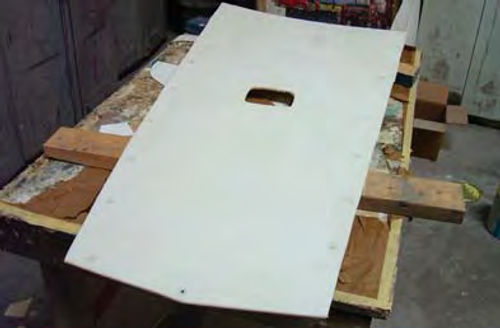
I start by making the center section. This is the only part of the headliner that will not be made in place on the roof. It will be a separate panel made out of Lauan plywood and will extend the full length of the roof. Once the side panels are completed, it will be put into place and anchored to the roof using the same GM-style plastic retainers I used to attach the door and quarter trim panels.
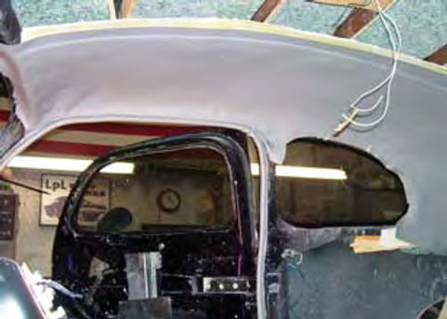
To make the panel visually appealing, I’ll make it 26 inches wide at the front and 20 inches wide at the rear (Photo 4). That gives me a starting place, so the next step is to make the side panels.
To make the side panels I use the same heavy cardboard I previously used to construct the templates for the door and quarter panel trim panels (July). I use the largest sheets possible and glue each one into place over my wooden framework until I have a base for the foam to be added next. This base needs to consist of at least three layers of cardboard to give it the needed strength to hold the foam and vinyl coverings.
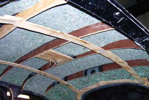
To make the curves at the back of the roof I cut the cardboard into smaller pieces and carefully sculpt the needed curves. I don’t use any staples here because once the sides have been covered and shaped the cardboard will need to be sanded smooth using a dual action sander with 80-grit sandpaper. Imperfections such as overlapped edges of the cardboard would telegraph through the foam and must be removed. The 80-grit will easily remove those edges (Photo 5).
A final note to Photo 5 is that I didn’t bother to extend the cardboard to the center of the roof panel as most of this area will be covered by the center section.
Bring on the Foam
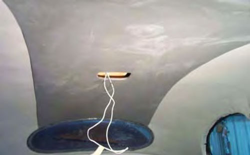
Next up is the foam padding (Photo 6). I’m using 1/4-inch-thick closed cell foam and I’ll glue it into place over the cardboard. To remove any wrinkles that form, especially in the corners, I pull the foam at the base of the wrinkle until the foam lies smooth. Any wrinkles that don’t pull out can be sanded smooth using 80- grit sandpaper.
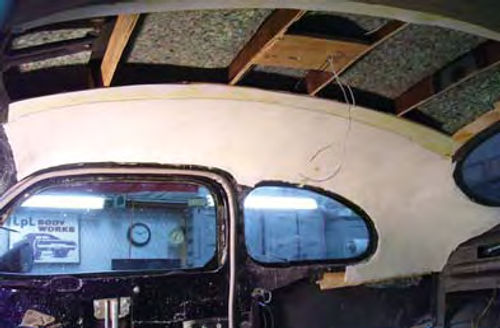
Notice in Photo 6 that the foam is cut along a very straight line where this part of the headliner will eventually meet the center section. This straight line is essential to the overall look of the headliner and was drawn by propping the center section base panel into place and using it as the pattern (Photo 7).
The last step is to cover the side panels with vinyl material.
I start by coating both the foam and the vinyl with adhesive. The adhesive is allowed to dry to the touch before attempting installation. This is a very important step as allowing the adhesive to dry will let me lightly stick the vinyl to the foam and if need be lift the vinyl to reposition it without worry of tearing the foam. Only after the vinyl is in place and wrinkle-free do I press it firmly to the foam (Photo 8).
I repeat this exercise on the left side and the roof is ready for the center section.
Since I’ve already constructed the base of the center section out of Lauan plywood all that is left to do is to add the plastic push-in retainers, (you can see those retainers already in place in Photo 7), cover it with a layer of 1/8-inch-thick foam, and cover that with the darker vinyl material. Why did I switch to the 1/8-inch-thick foam and not use the 1/4- inch-thick foam? Using the thicker foam would make the edges of the center section stand proud of the side panels and create a shadowing effect. The thinner foam keeps the panels flush with each other and prevents that shadowing effect. How does the final product look? I think it looks great (Photo 9).
The Console and Carpet
Carpet first, then console? Or is it the other way around? Actually, it’s both. I need at least some of the carpet installed before the console can be mounted, but because the console will be built in place I’d rather not have all of the carpet installed. Building the console in place means a lot of crawling in and out of the car, a lot of wood splinters from the construction of the console, and errant drops of glue hitting here and there inside the car as I cover the console with the dark gray vinyl. This is no environment for pristine carpet.
But then I want to sit the console on top of a carpeted drive shaft tunnel so that means some of the carpet must go down. I’ll start by covering the floor pan with a layer of rebond padding.
As you move through the next few photographs notice that the side trim panels are not in the car. Leaving them out will let me extend the floor pan carpet, once it is installed, past the bottom edges of the panels and that ensures that once the trim panels are installed the carpet will tuck neatly beneath the trim panels with no gaps or exposed areas of the floor pan showing.
Some Carpet and Padding
Needless to say, the floor pan must be clean and dry before you place the rebond padding. This is very important as the carpet to be installed over the rebond will take quite a beating. It must be securely anchored to the floor to prevent being torn, unraveled or pulled up. That starts by getting the rebond good and stuck.
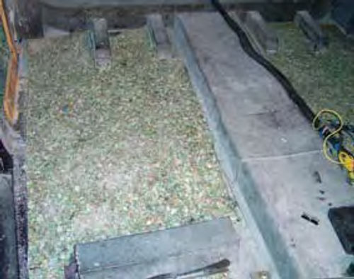
The rebond padding is glued into place (Photo 10). I’m still using 3M #8090 Super Trim Adhesive to get everything stuck into place. Notice that I didn’t pad the drive shaft tunnel. No need for padding here as the console will cover the bulk of the tunnel. Also notice that I left an inch of space between the rebond padding and the edges where the carpet will tuck under the side trim panels as well as along the sides of the drive shaft tunnel and around the seat mounting brackets.
Out on the edges this reduces the amount of material build-up that has to be forced beneath the side trim panels once they are installed. Along the drive shaft tunnel and around the seat mount brackets this allows me to cover these areas with scraps of carpet, (Photo 11), then allow the floor pan carpet, once it is installed, to overlap this selvage edge for a clean look.
Console Construction
The plan calls for a console that extends the full length of the cab. It will start just underneath the center of the dash and work its way to the rear of the cab where it will transition into a center armrest for the rear seat passengers.
The console also will serve as a conduit for the wiring that leads to the rear of the car and for that reason it will become a permanent fixture. Once completed, the console will give the illusion of being two separate pieces, a front section and a rear section. That’s because the rear section will only be half as wide as the front section.
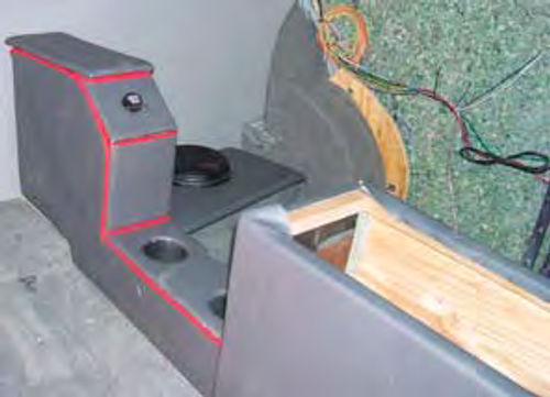
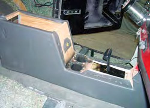
As mentioned above, the rear section will basically be an elongated armrest. I’ll add a couple of cup holders for passenger convenience as well as a power outlet to plug in those digital gizmos kids can’t seem to do without these days (Photo 12).
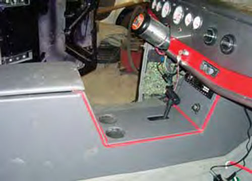
The forward section will be a little more complicated. Up here I need the rear portion of the front section to be elevated to a height comfortable enough for the driver to use as an armrest. As measured from the floor pan this height is 15 inches (Photo 13).
The top of the forward armrest will be a flip-up door leading to a storage compartment below. I eliminated the glove box in the dash, so having someplace to store things like vehicle paperwork is very important.
I’ll bring the front piece of the forward section up almost vertically and let it disappear just behind the face of the dash. This will be the perfect place to mount the stereo.
Construction is very simple. I use a length of 1/2-inch-thick plywood to form the base then build up each section using additional pieces of 1/2-inch-thick plywood mounted vertically on the base (Photo 14).
The sides of the console are cut from a sheet of Lauan plywood and stapled to the console frame. Once the sides are in place they are covered with a layer of 1/4-inch foam and the dark gray vinyl (Photo 15).The top portions of the console are fabricated on the bench before being attached to the framework using the GM-style plastic push-in retainers. The result of all this work can be seen in Photo 13. The design is pretty basic but it is very functional.
The Finishing Touches
A lot of hard work has already gone into fabricating the interior for the ’46 so now it is time to start putting all of the pieces together.
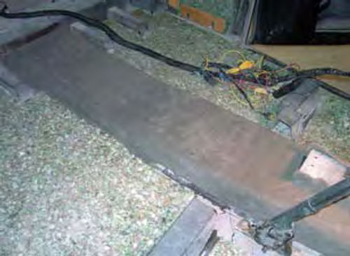
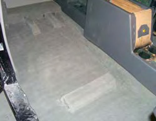
I’ll start by taking care of some lastminute details, the first of which is the floor pan carpeting (Photo 16). The carpet is glued in place over the rebond padding. Notice that I also covered the seat mounting brackets and how clean the seam line is between the floor carpet and the console carpet.
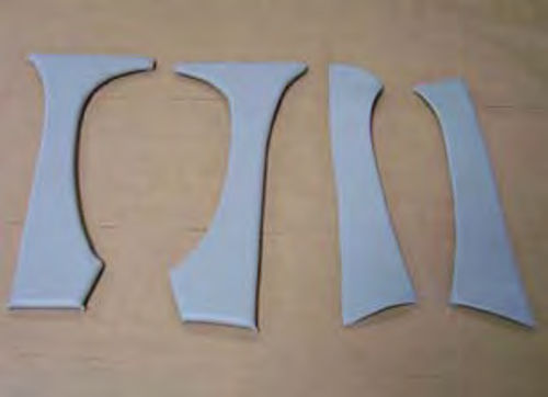
Next are the covers for the door pillar and windshield posts. To make these panels I cut matching pieces of Lauan plywood, two for the windshield pillars and two for the center door posts.
I then covered all four pieces with 1/8- inch-thick foam and the light gray vinyl (Photo 17). A little silicone adhesive will be used to hold them in place.

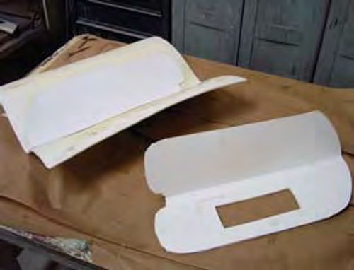
After that I covered the sun visors using the light gray vinyl. Luckily I still had the frames of the old visors.
I start by refinishing the frames with the same metallic gray paint I used to paint the dash.
Next I trace the outline of the old visors onto sheets of cardboard adding an inch all around. The idea here is to have enough cardboard to sandwich over the old visor. Since passengers always need a mirror I took an auto parts store mirror and glued it to the old visor.
After the glue dries, I add 1/8-inch thick foam to the remainder of the visor (Photo 18). That gives me a flat, smooth surface to glue my new cardboard covers over the old visors.
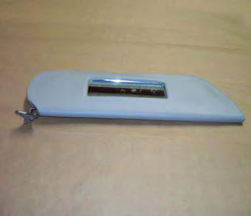
To complete the new covers I cut an opening for the mirror in the right hand visor then cover both covers with 1/8- inch-thick foam (Photo 19). Finally, the new visor covers are covered with the light gray vinyl then wrapped around the old visors. The result is a couple of very nice-looking visors (Photo 20).
An Upholstered Trunk
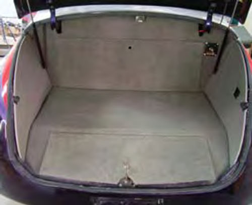
The trunk compartment gets basically the same treatment I gave the cab. I start by making new side panels using the light gray vinyl then cover the floor pan with carpet (Photo 21). Also notice in the photo that I added a Painless Performance battery cut-off switch (upper right rear corner).
What’s the hole in the right trim panel? I’ll be adding a switch panel here that has a switch for the trunk light, a pushbutton to open the driver’s door, and an emergency switch to open the license plate pocket.
Resources
LPL Body Works
5815 Contented Lane, Amarillo, TX 79109 www.lplbodyworks.com
Producers of paint and body repair DVDs
Crest Industries
231 Larken Williams Industrial Court, Fenton, MO 63026. ; www.crestmidwest.com
Painless Performance Wiring
2501 Ludelle St. Ft. Worth, TX 76105. ; www.painlessperformance.com
The Eastwood Company
263 Shoemaker Rd. Pottstown, PA 19464. ; www.eastwood.com


