How -to Rebuilding a Starter, Pt. 1
It May Be Time to Disassemble & Rebuild Your Vintage Starter. So First, We’ll Gather Tools & Start an Inspection.
THERE ARE SEVERAL things that can cause a vehicle to have difficulty starting, and among them, obviously, is the starter itself. It may spin the engine too slowly, or possibly not at all. But, before proceeding, you will need to first verify that the starter is indeed the problem. This is typically determined with the aid of a carbon pile load tester, or induction amperage meter that can be clamped over the starter’s battery cable to determine the amount of current draw.
Problems with the battery, charging system, or an electrical drain can often display the same symptoms. Some situations, such as when the starter spins but the engine doesn’t, are obvious mechanical problems. Usually this is a problem with the starter drive unit. This can also be due to badly damaged teeth on the flywheel, so a complete visual inspection of the flywheel would be necessary as well.
A Classic Starter
The subject for this series of articles is a typical Delco starter. This one is on my 1966 Chevelle Malibu, but the unit remained virtually unchanged for almost three decades.
In this instance, the problem is that on rare occasions the starter will spin but the engine doesn’t. As previously mentioned, this typically is a mechanical problem, but regardless, we will completely inspect all the components and replace the usual wear items.
The Starter Solenoid
Before going any further, let’s take a moment to talk about the starter solenoid. This solenoid acts to engage the starter drive with the flywheel, and energize the starter. Solenoids are typically replaced as a unit or simply reused. If you can hear the starter engage with the flywheel and attempt to rotate the engine, then the solenoid is doing its job. If there were any question about the starter solenoid condition, it’s easiest to check it while it’s still hooked up and in the vehicle. You can either perform a few quick tests to determine its condition (see the March 2009 Auto Restorer article “Battery & Starter Troubleshooting” for more on this), or simply choose to replace it. The choice is up to you. Over the years I have seldom experienced solenoid problems with Delco units.
An important note to remember here: Don’t be misled by “clicking sounds.” If you hear a clicking sound coming from the starter solenoid when trying to start your vehicle, this typically is an indication of low voltage due to poor cable connections or battery related issues (either state of charge or condition), not a defective solenoid. I am not saying that it’s not possible, but usually the problem is elsewhere.
Begin By Removing the Starter
Once the determination has been made that the starter requires service, the first step is to remove it.
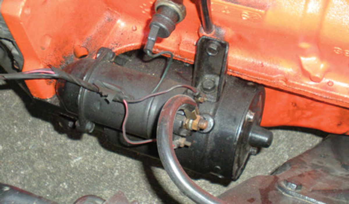
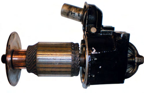
In most cases, freeing the unit from the engine is straight forward. The starter shown in Photo 1 is on a 194 CID six cylinder engine. It doesn’t get much easier than this.
Disconnect the battery ground cable; then the wires from the starter solenoid; remove the rear support bracket and two bolts that secure it to the engine block and it’s free.
To avoid any confusion, it never hurts to label and identify the location of each wire. Many vehicles will offer additional obstacles such as exhaust pipes that may need to be loosened to achieve starter removal. You might even find it necessary to loosen or disconnect an engine mount, and raise the engine slightly with certain vehicles. Often, twisting and rotating the starter to odd positions will give the additional clearance needed for removal, without the need to loosen or remove anything else.
If that works, remembering the position the starter was in when it finally came out will save you some time when replacing it.
If you’ve never removed a starter before, you might be surprised at how heavy it is. This one tips the scale at just less than 20 pounds. In other words, be prepared once the last bolt threads out.
Some Quick Safety Advice
Before you get underneath a raised vehicle to start your inspection, remember to secure it on properly placed jack stands, and chock the wheels as well. If you aren’t sure, check your shop manual for proper jack stand placement.
Always keep in mind that jacks are for lifting only.Never, ever consider getting under a vehicle while it’s supported with a hydraulic or mechanical jack.
Flywheel Gear Inspection
My particular problem could be with the starter, flywheel or both, so a visual inspection of the ring gear portion of the flywheel is a must. This is never a bad idea, anyway.
Once the starter is removed, view the flywheel’s teeth through the newly created opening.
Your concern is the side of the flywheel where the drive engages. Using a mirror may aid you in having a good view of the teeth. On this vehicle there is a protective cover that can be removed once the starter is out, giving a larger area to view. However, on many vehicles that’s not an option.
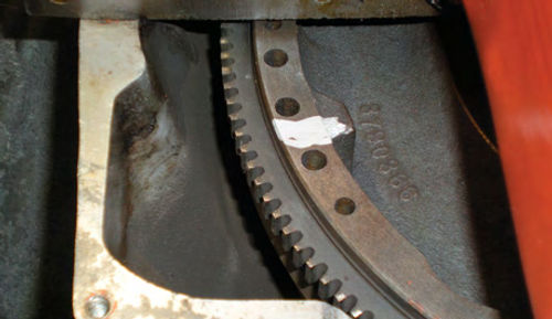
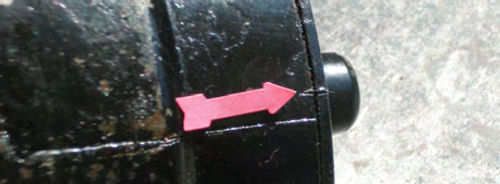
Make a reference mark on the back of the flywheel with chalk or something similar, asin Photo 2. This way it’s easy to tell when a complete revolution of the flywheel has been made.
In some instances, a flywheel wrench can be used to rotate the engine, making this an easy one-person inspection job. Otherwise, have a helper rotate the engine by hand, while you view the flywheel. This makes the task easier. Usually a socket can be used on the crankshaft pulley bolt and rotated with a long ratchet or breaker bar. If that’s not possible, try using the fan blade for leverage to rotate the engine or even use a wrench on the alternator nut while pushing inward on the drive belt. This will also work.
The ring gear doesn’t have to be absolutely perfect, and unless it’s new, it’s highly unlikely it will be.Isolated areas of minor damage may be acceptable.
When inspecting a questionable area, decide if it is damaged to a degree that the starter would slip and grind if it tried to engage there.
If the answer is yes, then the flywheel will require a new ring gear or complete replacement. If you find teeth that are rolled over or rounded slightly, consider using a Dremel tool with a small stone to clean them up.
My inspection revealed several spots of minor damage, but none too major to preclude working with them.
Rebuild, Exchange or Buy?
At this point you will be faced with the decision of rebuilding the starter yourself; exchanging it for a rebuilt unit, or possibly even securing a new starter.
It’s certainly hard to argue against a new starter if one is available for your vehicle. These are quite expensive, though, so if you’re working within a budget, decide if that is really where you want to spend your money.
Depending on the type of vehicle you own, you may not have the option of buying a new starter, or, for that matter, even the option of an off-the-shelf rebuilt unit.
In any case, consider rebuilding the starter yourself. Whenever possible, I prefer to save and repair the parts that came on my vehicle. It’s not that I am a purest and need to maintain “matching numbers,” I simply enjoy doing the repairs. Maybe I just like to know every nut and bolt on a first-name basis. Besides, the repairs and testing are fairly simple and by doing the work yourself, you can be certain of the quality of the parts used in rebuilding the unit. In addition, the problems experienced with your current starter are well-known to you. While not likely, it is possible to purchase an off-the-shelf rebuilt unit that has problems of its own.
Tools You’ll Need
Tools and other items that will be used in this project are of the basic variety: a block of wood, pick tool, bench vise or drill press, an armature growler with continuity test leads,(optional) using a voltmeter, jumper lead, and a 12-volt car battery. A hand impact tool will be needed if the field coils require removal, and if you decide to bench test the starter before installation (highly recommended) a remote starter button and induction amperage meter can be useful.
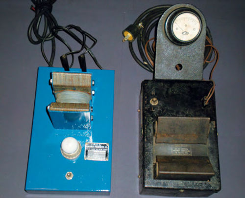
Keep in mind that growlers come in different shapes and sizes. Most will have test leads for checking continuity with a low-wattage bulb as an indicator light. If you decide to purchase one, this is an option worth holding out for, as it gives a little more of a “punch” using AC current to test components than you will achieve with DC current. Photo 3 shows two typical units. The unit to the right is a heavier duty unit as you might guess from its size. It has a high- and low-level test range for the armature, and the “open core transformer” is considerably larger than the other unit.The indicator light is located inside the unit, and holes on either side allow the user to see light emitting during testing. In addition, this unit added a buzzer that also comes on with the light when continuity is detected. As you might expect, you can look for these at your local auto swap meet and even, on occasion, they will surface at a weekend flea market. They usually run anywhere from $10 up to around $40 for nicer ones. Don’t be afraid to take a chance on one that, say, needs a new power cord if the price is right. My luck has been 100% with ones I have purchased.
The armature growler is not something you will use that often, but, nonetheless, it can be a handy addition to your automotive tool collection. Its uses go beyond just starters; it also can be used in testing generator armatures, and its test leads can be used on many electrical tasks like alternator and generator rebuilds, to just simply testing switches. I would, however, avoid using AC current for testing alternator diodes, as there is the possibility of damage.
We will talk more about this tool when we reach that portion of the rebuild. If you don’t wish to purchase a growler, you can proceed with the overhaul and either have the armature tested by someone who has one (typically anyone who specializes in automotive electrical repair), or just perform the continuity and “smell” tests using a voltmeter; your vehicle’s 12-volt battery; and your nose. While not the best, this evaluation, in addition to the process of elimination as we inspect the remainder of the starter, will in most cases successfully do the job.
Unit Disassembly
Before beginning the disassembly, clean the starter off, removing any heavy grease and dirt.
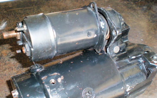
The solenoid is removed first. It’s connected to the starter’s nose section with two horizontally mounted screws, and a third one located at its base. This is referred to as the “solenoid to starter motor terminal connection.” There is a rubber insulating grommet surrounding this starter terminal, which is actually the flat field terminal connection. Remove these three screws and rotate the solenoid 90° in either direction. There is a spring inside the solenoid that keeps the starter drive in the retracted position. The spring will give a gentle push once the solenoid is free. Lift the rear of the solenoid up to clear the terminal connection as shown in Photo 4, and then remove the spring and solenoid. Set it aside for the time being.
Make an alignment mark: Doing this on both the field housing and rear cover will make replacing the two long through bolts less time consuming when it comes to reassembly. A small chisel will do well, and you can see the results in Photo 5. If you prefer, mark it with a file. Scribing with a pick tool might be too light and would possibly be concealed if you decide to repaint the unit. No need to worry about marking the nose section, as it has an alignment pin to position it properly.
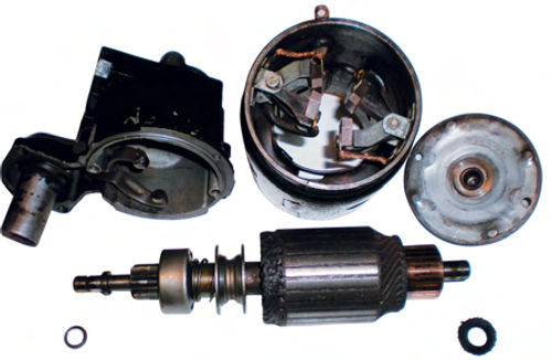
Remove two bolts and open up the starter: Using a 3/8” socket and a ratchet is a quick way to loosen and remove these bolts. Once removed, you now have four components ready to be separated. There is no right or wrong approach. I usually remove the rear cover first. It may require a light tap or two with a hammer to loosen it from the housing. Next grab the nose section which will be connected to the armature via the starter drive and slide it straight out. A bit of twisting will disengage the shift lever from the starter drive. Once removed, slide the loose washers off at each end of the armature to avoid losing them. Your workbench may now resemble Photo 6.
Identifying the Components
Before going any further, let’s take a moment to identify the components.
The armature is located at the bottom of Photo 6. It includes the following:
The starter drive (also referred to as an overrunning clutch) is mounted on the left side of the armature, and is the mechanical link between the starter and engine.
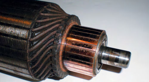
Core frame and winding. This is the large diameter (central area) of the armature.
Commutator. The copper area where the brushes ride to the far right of the armature.
Note the two washers. The small one to the left is the steel “thrust” collar, while the larger one on the right is the leather “braking” washer.
The Drive or Pinion Housing is shown in the top left of Photo 6. The solenoid bolts up to it; and it functions to engage and retract the starter drive. The front bushing is located in its end. It also includes the following:
Solenoid Plunger. The cylindrical-looking piece connected to the top of the housing that fits into the starter solenoid.
Shift Lever. This is the fork-shaped part inside the housing that moves the starter drive in and out of engagement with the flywheel.
The Field Housing or Frame is found top center in Photo 6. It holds the field coils and pole shoes as well as the brushes, brush holders, springs and retaining pins.
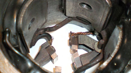
Pole Shoes. The four,somewhat rectangular-shaped pieces of iron located in the center of each field coil seen in Photo 7. These are retained by a countersunk bolt that enters from the outside of the field housing. They retain the field coils in place, and function like large magnets when the field coils are energized.
Field Coils. These are the coils of copper “wire” located in the field housing, and are covered with black plastic insulation as you can see in Photo 7. The color of the insulation may vary, and isn’t important. Older coils may be found wrapped in a cloth-like tape, similar to something called “friction tape.”
End Frame (Rear Cover). Shown in the top right of Photo 6. It holds the rear bushing; positions the long through bolts, and sandwiches all together
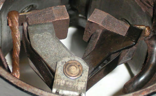
Brush Holders, grounded and insulated. Shown to the left in Photo 8 is one of the grounded brush holders. They are made of metal, and have an exposed copper wire connecting the brush to the frame. To the right in Photo 8 is one of the insulated brush holders. They are made of a non-conductive composite, and the wires connecting to them are insulated and connect to the field coils.
It’s not unusual for components to be referred to using several different names, but the ones given here are probably the most common.
Testing the Armature
There will be several other component disassemblies, but this is a good time to pause and test the armature. Leaving the starter drive in place makes it easier to rotate the armature when testing it on an “energized” growler. The drive will be replaced once we know the armature is in good condition.
1. Visually inspect the armature. The commutator is the area where the brushes ride. It is actually comprised of many flat bars. The commutator seen in Photo 9 has 27 separate bars, each one with a heavy wire soldered to it.
An open circuit in the armature can be identified by a badly burned (discolored) commutator bar. Inspect the soldered connections of the heavy wires at the end of the commutator for any that may have come loose. They can be re-soldered. In general, you should expect there to be a uniform appearance to the armature. The commutator should be smooth. If it has some minor roughness or scoring, the commutator bars can be turned on a lathe, or even lightly polished with something fine like 600-grit sandpaper. Make sure to remove any abrasive residue that remains from using sandpaper. Additionally inspect the armature’s core frame for scuff marks. Look inside the field housing at the iron pole shoes for shiny corresponding scuff marks. A loose pole shoe or worn bushings is most likely the cause. These conditions will cause the magnetic field to momentarily break down. This will slow the starter’s rotation, or even keep it from rotating at all. Usually tightening the loose pole shoe or replacing worn bushings will correct the situation. (We will talk more about that later.)
Another possible cause is a bent armature. If you have a machinist friend, he or she could rotate the armature in a pair of “V” blocks and inspect it for run-out (wobble in its plane of rotation).
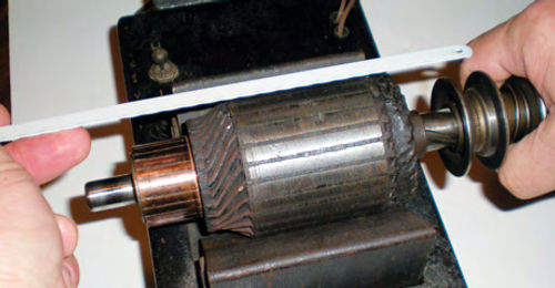
A very primitive inspection can be done by rolling the armature on a smooth table top, or better yet, support it in between its own bushings without the field housing as shown in Photo 10. You will need to secure both the drive housing and rear cover so they don’t roll around. Gently clamping them down to the workbench will do. Now you can rotate the armature while making a visual inspection and determine if it’s bent. Once you’re satisfied, it’s time to utilize the growler for testing.
2. A short circuit test. To test the armature winding for a short circuit, position the armature in the “V” of the growler’s transformer. Turn on the transformer. Use one hand to rotate the armature while the other hand holds a hacksaw blade (or any thin steel strip) just above the armature as shown in Photo 11. If a short circuit is detected, the hacksaw blade will vibrate when it is directly above it. Once it has passed this test, switch off the growler’s transformer.
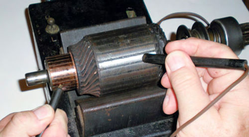
3. Testing for a grounded armature. Turn on the growler’s test leads. This test is to determine if the armature windings have an unwanted ground. Touch one test lead to the commutator and the other to the iron core frame as seen in Photo 12. There should be no continuity, thus the light should remain off.
Testing Without a Growler
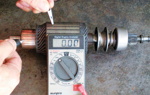
If you are testing without the aid of a growler; perform the same visual inspection we did in step #1 under testing the armature. Also smell the armature; does it have a burnt electrical smell? This is a very obvious odor. If the answer is yes, the armature may be bad. At this point it would be money well spent to have someone test it on a growler for you. If, however, it appears to be OK, continue on and use your voltmeter and 12-volt battery to check for an unwanted ground. The voltmeter’s positive lead is connected to the battery’s positive post, and the negative test lead touched to the commutator. A jumper wire is connected to the battery’s negative post and the other end is touched to the armature’s iron frame as shown in Photo 13. If the voltmeter indicates any voltage, the winding is grounded and the armature will require replacement.
Once you have completed these tests on the armature, set it aside.
Testing the Field Coils
Don’t put the growler away just yet. You can use its test leads for checking the field coils. And if you’re using your voltmeter and 12-volt battery, keep it hooked up. We will be performing continuity tests on the field coils similar to those performed on the armature.
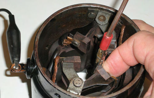
Open Circuit Test. Connect either test lead to the flat field terminal. This Is easy to spot; it protrudes from the exterior of the field housing. This was connected to the base of the solenoid, so if there is some paint on it; make sure to establish a good connection. Connect the remaining test lead to one of the insulated brushes. The indicator light should come on if using a growler, and if testing with a voltmeter, it should indicate battery voltage. While still connected, rock the brush holder back and forth through its range of motion using your finger as shown in Photo 14. Continuity should remain uninterrupted. Now move the test lead over to the remaining insulated brush and repeat the same procedure. Once again, you should have the growler light on (or battery voltage on your meter) all the time. Any interruptions indicate an open in the wiring. Repairing a bad connection, or replacing the field coils are usually the options.
Next: We’ll continue our testing of the field coils, consider some repairs and start replacing the “normal wear” items.


