Diagnosing and Replacing an A/C Compressor Clutch
When the Air Conditioner Starts to Pump Out Warm, Humid Air, Something Needs to Be Fixed. We’ll Start With Some Troubleshooting Steps.
Even though central Florida experiences some cold temperatures at times; you can almost bet you will use your vehicle’s air conditioning (A/C) at least once over the period of a week or two in the winter. In addition, the air conditioner is engaged on most vehicles (at least older GM products) when in the defrost/defog mode when the ambient temperature is above freezing (usually above 40° F). This aids in removing moisture that forms on the inside of the windshield, and also keeps the oil in the system from sitting idle for half the year. In turn, this helps to keep seals oiled and that reduces the chance of refrigerant leaking.
So for those living in Florida, A/C can be considered a year-round necessity; unless your vehicle is like our ’66 Malibu where “natural air conditioning” is as good as it gets.
First Cool Air…Then Warm and Humid
The past winter saw some of our warmest temperatures on record with summer-like high humidity, and our A/C-equipped 1986 Caprice was getting the majority of our road time.
The A/C had always worked well, requiring only minor service over the 20 years we’ve had it, but unfortunately it’s not a perfect world, and eventually it started to act up. It might perform fine for a while, and then suddenly that cold dry air coming out the vents would start feeling warm and humid…and you quickly realized that the AC was no longer working. As long as the system remained on it would at some point decide to start working again. It might take 10 minutes or more but eventually it would return, and for a short time it would cool perfectly. The fan speeds were not affected, they all worked fine. Just the ability to remove heat from the vehicle was lost.
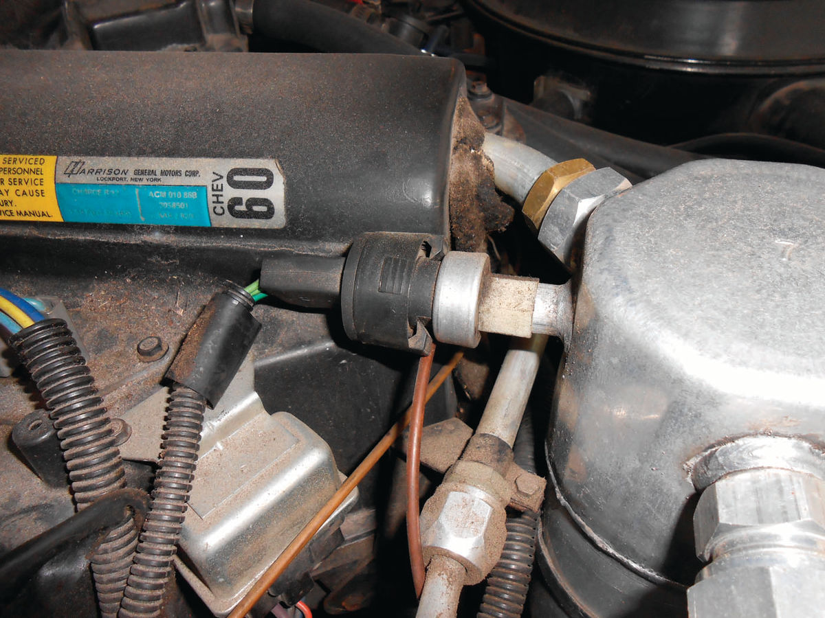
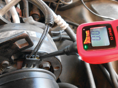
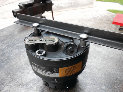
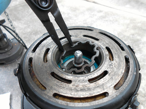
With the hood open a visual inspection was made to observe if the clutch was engaging as it should. Under most normal operating conditions it should cycle on and off, and continue to repeat this as long as the A/C is on, thus the system name “Cycling Clutch Orifice Tube” (C.C.O.T.). On extremely hot humid days, especially if the fan blowing over the evaporator is set to high speed, the clutch may stay engaged, and that’s normal. The clutch cycling is controlled by a pressure switch in the low pressure side of the system. More specifically, on this vehicle, it threads into the top rear of the accumulator as pictured in the center of Photo 1. It’s connected through a Schrader valve, so it can be removed without the necessity of discharging the system’s refrigerant. When the pressure on the low (suction) side of the system drops to a predetermined point (25 psi), the pressure switch opens, and the 12V power to the A/C Clutch is turned off.
Ambient temperature also has an effect on the system pressure. As the temperature drops, so does the system pressure. That’s also why the system won’t engage when ambient temperature is close to or below freezing. While the pressure switch only functions to supply 12V power to engage the clutch, or open the circuit disengaging the clutch, that does a couple of things. When the lowside refrigerant pressure falls to 25 psi the switch opens the electrical circuit, and this allows the low-side pressure to rise, keeping the evaporator from freezing under normal operating conditions. If it didn’t do this, the evaporator would freeze up like a block of ice, and the vehicle would quickly lose its cool.
Had there been a refrigerant loss in the system causing the low pressure, it would protect the compressor from running without oil by opening the circuit to disengage the clutch. Oil is carried through the system by the refrigerant, so low pressure could also be a sign there is too little refrigerant in the system to return the oil back to the compressor. It’s worth knowing some basic information with regard to how the cycling clutch system works. More in-depth information can be found in the vehicle’s factory service manual or other professional manuals like those offered by Mitchell.
In the case of the Caprice, with the A/C turned on the compressor clutch would usually engage when the vehicle was initially started. It may cycle properly several times with all working fine, and then after running for a short time it would disengage, but not re-engage.
Air conditioning gauges could be connected to check the system operating pressures, and there is nothing wrong with doing so, but in this particular case that really doesn’t seem necessary. It initially cools fine as long as the clutch is engaged or cycling as normal. This indicates that there is sufficient refrigerant in the system, so low pressure from refrigerant loss is not the problem.
Troubleshooting the Situation
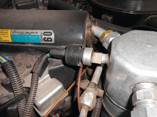
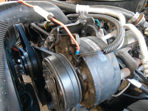
First don’t overlook the obvious, make certain the wires and connections are good at both the pressure switch and the compressor clutch. The plug for the compressor was certainly showing its age, so a new one was purchased. It was soldered in place, and then protected with heat shrink tubing. Photo 2 shows a comparison of the two. Whether or not this had anything to do with the problem being experienced isn’t the issue. It could be causing an intermittent problem or likely will in the future. Quite simply, replacing this weak point with a good solid connection is good preventative maintenance at the very least, and eliminates any questions.
There are several troubleshooting charts in the service manual, but it would seem simple enough to check if the clutch is receiving the voltage signal when the A/C is called for, and that there is also a good ground circuit. This is easily verified with a test light or power probe tool.
It isn’t necessary to have the engine running when checking the clutch on this vehicle. Just turn the ignition to the “On” position, and then using the dash controls, turn on the A/C.
The clutch should engage and make a loud click when doing so. This time however it did not, so that allowed us to see if it was receiving the voltage signal when the AC was requested, but the clutch not engaging.
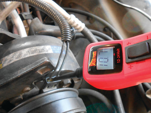
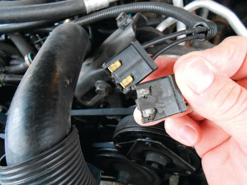
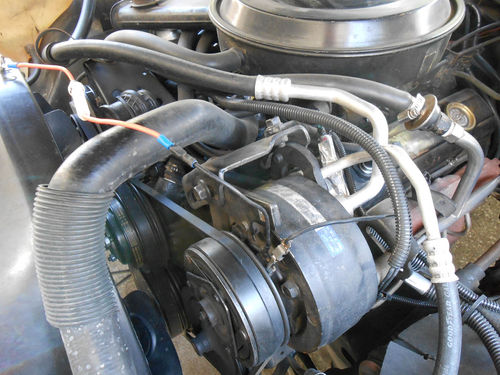
Using the power probe as seen in Photo 3 to back probe the connector, it quickly identifies voltage going to the coil, and in Photo 4 a confirming green light indicates ground at the other connection. Turning off the AC request, the voltage signal disappears but the ground remains constant. As long as you have a basic test light in your toolbox, it will work just as well.
Looking at the troubleshooting chart in the manual, the first test they show for checking the compressor clutch coil operation is to “apply 12V directly from the battery to the coil hot lead.” Having made our check with the power probe there is no doubt which terminal that is. This test may sound somewhat redundant after just making the Power Probe check, but it’s possible the 30-year-old original wiring might be putting up too much resistance and not carrying sufficient current.
With the ignition off, a heavy gauge jumper wire is connected by back probing the plug at the clutch, and then connecting to the battery positive terminal as seen in Photo 5. It’s a good idea to use a fuse-protected test lead in the event you accidentally make contact with a grounded surface. If you choose to use an unprotected jumper lead, be cautious; it can be easily grounded when trying to establish the connection at the compressor. This test made no change, the clutch did not engage.
Next apply an external ground to the other terminal. At this point it is easiest to remove the plug and make both connections directly to the clutch as shown in Photo 6. Carefully connect the battery positive connection first, and then complete the ground connection. In this instance a good ground was available at the front valve cover stud. Still the clutch didn’t engage, so no doubt there is some issue with the clutch.
So, What Do We Know At This Point?
The clutch is receiving the voltage signal with the ignition on and the A/C requested.
The ground is also complete as indicated with the test light.
New heavy-gauge jumper wires were used to bypass the existing wiring and the clutch still didn’t respond.
At this point the manual states “repair clutch coil.” In other words, replace it.
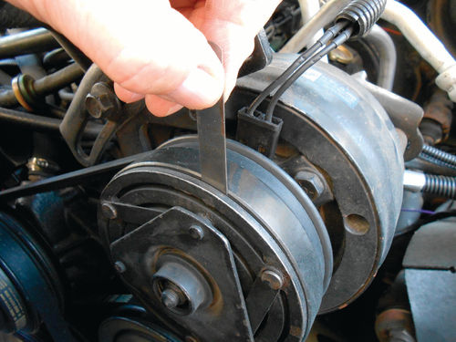
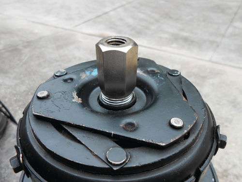
But there is still one more possibility. The clutch adjustment (air gap) may be too great. This isn’t mentioned in the manual, and might be considered unlikely, but that was the problem with our El Camino many years ago. It too would engage when it wanted to, performing much like the Caprice is doing. The air gap should be .020”-.040”. By just looking at the clutch on the El Camino the gap appeared large, and a feeler gauge confirmed it. In the case of the El Camino, adjusting the compressor clutch air gap was all that was needed to correct the problem. With the Caprice, the clutch adjustment was checked with feeler gauges and .028” fit well as seen in Photo 7. So that’s within specification and can be eliminated as a possibility
Replacing the Compressor Clutch
Reading the replacement procedure in the manual seems to make it more complicated than it really is. This is partly because replacing the bearing is included in the process. Note that there are at least two clutch variations. One has a rounded appearance with six perimeter bolts in it. This is referred to as a four-pole clutch. The other has a much flatter, squared off look and is called a six-pole clutch. Regardless, new clutches generally are sold with a new bearing installed so those details can be skipped. While they both function the same, their replacement procedure will vary slightly, as I found out. There are several special tools that will be required, and what’s needed will depend on the type of clutch you have.

To do a typical four-pole clutch the tools pictured in Photo 8 will be required. At top left is a special driver for installing the rotor and coil assembly. The tool with the red handle is used to hold the drive plate while allowing you to remove the nut from the compressor shaft. The puller along with the spacer bushing directly beneath it are used together to remove the rotor and coil assembly. During removal, the bushing transfers the puller’s screw pressure to the nose of the compressor. Pressure directly on the compressor shaft could cause damage. Those two short arms faced away from each other fit into a recess in the rotor for removal. Of course different arms are required for different style clutches. Below the puller are a couple of tools that look similar. To the left is the tool for removing the drive plate, and to the right the tool for installing it. The feeler gauge is used in making the final clutch adjustment. In addition you will need a pair of snap ring pliers, and the usual hand tools.
Check with your local parts store to see if these special A/C tools are available for loan if you purchase the part from them. Don’t be surprised if the tools look different, especially the puller. In the Chevrolet service manual they show a three-jaw pulley used to remove the rotor; not at all like the fixed two-arm puller shown.
If you have access to an old “junk” compressor with the clutch still on it, it never hurts to do a practice run before starting on your vehicle. This will help you become familiar with the procedure, and have a good idea of what to expect.
Practicing On an Old “Test” Compressor
For this practice procedure, an old R-4 compressor that came off the Caprice years ago will be the test subject.

You will want to secure it in a vise. Naturally they make a fixture to hold it, but one can easily be made from a short length of 1” angle iron by drilling a couple of 3/8” holes, 5 ¾” apart. In addition, two spacer bushings are necessary. A pair of bushings from a GM brake caliper hardware kit worked fine. If you’re like me, and have a collection of old takeoff parts, dig around and see what you have. To secure the compressor to the fixture, you can either use the correct thread bolt (metric in this case), or use a slightly smaller diameter through bolt and 4½” long should do. Then nuts can be threaded onto the ends of the through bolt, securing it to the fixture. This works fine for clutch replacement.
If you have the correct metric bolts handy, great! Photo 9 shows the homemade fixture secured to the compressor.
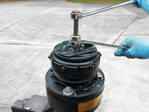
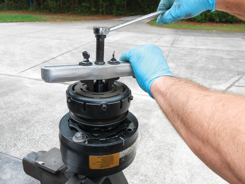
Start by removing the 14mm shaft nut using the red-handled spanner tool to secure the drive plate and the appropriate socket and ratchet as shown in Photo 10. Next is to remove the drive plate. There are threads on the inside of the hub that the puller must secure to. Typically they are full of dirt, so it‘s a good idea to use something like a small toothbrush and clean them out as best possible. Back the pressure screw out of the drive plate removal tool, and then thread the nut portion fully into the drive plate (but no need to force it) as shown in Photo 11. Put a dab of grease on the end of the pressure screw and thread it back in. Use a wrench to hold the retaining nut portion of the tool, while using another wrench to rotate the pressure screw as you see in Photo 12. This photo also shows the common four-pole clutch I’ve mentioned.
There are six perimeter bolts that make it easily identifiable. Unless you are replacing the bearing, these bolts can remain undisturbed.
As the pressure screw is tightened, the drive plate will pull away from the clutch rotor until it is finally free. There is a keyway machined into the drive plate and shaft, so don’t let the key escape.
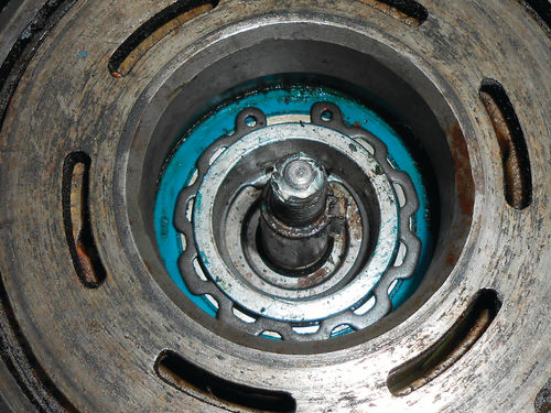
Now look at Photo 13 and notice the snap ring securing the rotor. A pair of generic snap ring pliers is all that’s needed to remove it as is being done in Photo 14. Note that the side of the snap ring facing outward should have a slight bevel. When replacing it, the beveled side should again be installed facing outward.
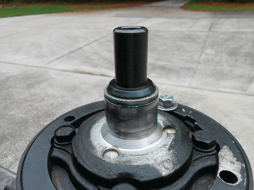
The rotor and coil assembly are now ready to be removed. The spacer bushing is placed over the shaft, resting on the nose of the compressor, and the puller is positioned so that the jaws engage with the groove in the rotor. The pressure screw is tightened against the bushing, and the rotor begins to pull free of the compressor with little effort as seen in Photo 15. This isn’t like removing a harmonic balancer from a small block engine. The puller can easily be held by hand while the pressure screw is turned.
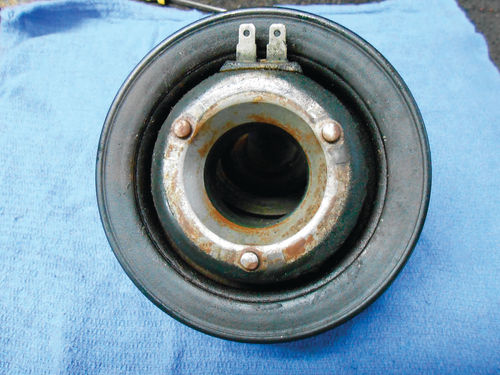
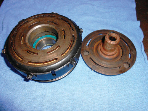
Photo 16 shows the removed rotor and coil to the left, and the drive plate to the right. The purpose of Photo 17 is to give you a clear view of how the bushing rests on the compressor nose during rotor removal. If you don’t have this spacer bushing, don’t attempt to remove the rotor until you do. Also notice in the photo the small locator wells equally spaced around the base of the compressor nose. These are used to index the clutch terminals during installation.
Photo 18 shows the back side of the coil with the corresponding bosses. This design allows three possible positions for the clutch terminals. If you were to purchase a new (or remanufactured) compressor they will make clock references like “12 o’clock.” This references the approximate terminal location when positioned on the vehicle. While this is unimportant during this practice run, it is essential when doing the real job. So remember to mark the location of the terminals before removing the old clutch assembly.
Next we’ll finish our practice run and then replace the compressor clutch on our Caprice.


