
How -to Tuning a 1965 GTO
This Tri-Power Car Was Pinging and Would Sometimes Stall. So, a Five-Pronged Approach Was Used on It.
THE OWNER OF this ’65 Pontiac GTO complained of “pinging” in high gear during moderate acceleration at 60 mph. At full throttle, however, there was no pinging.
The startup from cold was OK but the car sometimes would stall while backing out of the garage. The idle was slightly rough after warm-up.
Engine Information
This ’65 GTO has a 389 CID V-8 equipped with “Tri-Power” carburetion and a 4-speed manual transmission.
The three carburetors are 2-barrel Rochesters. The center carburetor is a 7025175 and the front and back carbs are both 7025179s.
Both end carburetors have no chokes or idle circuits. The mechanical throttle linkages are “progressive.”
Our Project Approach
The approach to a good tune-up is to service the battery-cranking system first.
Second, measure the compression to ensure that you have a sound engine for a good tune-up.
Third, service the ignition system.
Fourth, test the fuel supply. Check the choke action on the middle carburetor.
And fifth, look for evidence of “dripping” fuel, with the engine off.
Then, start the engine, check the plug firing voltage, adjust the base timing to specification and look again for fuel drip, this time at idle.
Measure total advance and, finally, adjust the idle rpm and idle mixture.
Note: What is “drip”? Drip is internal leakage in the carburetor from the main circuit discharge nozzles and/or the accelerator pump circuit. Causes are usually high fuel levels in the bowl and/or the accelerator pump circuit outlet leaks.
Cranking System Performance
The starter “sounded good” and the voltage was 10.7 during cranking with the distributor end of the coil wire grounded. However, the ground voltage was 0.6 during cranking. Not good!
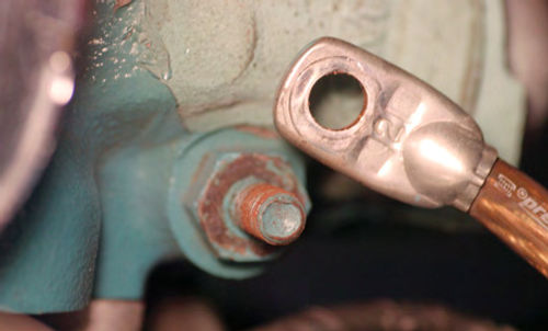
The culprit was the head bolt/stud, the ground point, located on the left front of the cylinder head.
In this case, remove the ground cable and the head bolt, clean and oil both the head bolt and the ground stud threads (Photo 1). Reinstall the head bolt, torquing it to specifications. Clean the battery ground connections and re-install on the head bolt.
After servicing all the battery connections,the cranking voltage was still 10.7. Simultaneously, however, the ground voltage was reduced from 0.6 down to 0.2 during crank.
The cranking sound was better and the cranking rpm was faster.
Engine Condition
Compression Check: A dry compression test was performed with all the plugs removed. The compression measured 180-190 psi on all cylinders during cranking. This Is good for a successful tune-up.
Crankcase Oil: The oil and filter were recently changed with 20-50wt oil installed.
Ignition Service
Spark Plugs: We “read” the spark plugs. All inner porcelains were a light tan in color. This is normal. It indicates the carburetor mixture is nearly correct.
The spark plugs were replaced with an AC R45S plug set. They were gapped at 0.035-inch.
The threads were lubricated with Permatex Anti-Seize, installed to seat contact, and torqued to 1/4-turn past the new washer seat contact.
If you’re re-installing the existing plugs and washers, lube the threads and torque to 1/8-turn past seat contact.
Note: When removing stuck plug wire boots, twist the boot and lift as they can easily be ripped.
Also, tool trucks have special tools to lift boots without damage.
During installation, coat the boots’ insides with silicone grease.
Distributor Service: This case history vehicle distributor is equipped with a Petronix electronic ignition system.
To service this system, loosen the ground screw located on the distributor plate and retighten. This breaks any possible rust or corrosion.
The mechanical advance and weights worked freely and were not rusty.
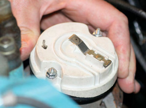
Twist the rotor to full advance; it should snap back. Remove the rotor and lubricate the mechanical advance mechanism with penetrating oil, especially beneath the top plate and main shaft. These do get sticky and rusty without lubrication (Photo 2).
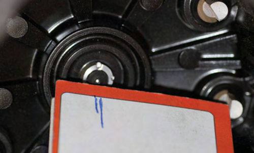
Measure the rotor gap as shown in Photo 3. It should be around 1/64-inch.
Use a business card to measure the radius from the center of rotation to the cap lug. Then compare this radius to the rotor radius. If the gap is more than 1/64-
inch, replace the cap and rotor.
Also check any new parts you may be using to ensure the correct rotor gap. If the gap is too wide, spark voltage is lost and can lead to ignition misfire. In addition, using an ohmmeter, measure the rotor resistance between the center point and the tip (Photo 4). It should be zero (0) ohms between the tip and the center contact. I have experienced several ohms of resistance caused by the rivet being rusted. In that case, install a new rotor.
Sand the crust off the rotor tip. This cleaning reduces the voltage required to jump the gap.
Knock off the crust buildup inside the distributor cap on the plug wire lugs.
Test the vacuum advance by pumping it up with a hand vacuum pump. Watch the plate move around 10° rotation. It should hold a 20” vacuum with- out leaking off. If it leaks, replace it.
Our GTO passed all of the above ignition tests.
Note: Vacuum advance units are usu- ally available at NAPA or CarQuest parts stores. Be prepared to give them the distributor serial number and match up the vacuum advance arm.
If a new vacuum advance can’t be obtained, send yours to S and N Auto Electric in Sacramento, California. They can rebuild the unit. (See the Resources list at the end of this article for more details on S and N.)
Spark Test: The coil output measured 50KV during crank; open circuit. The coil fired a fat blue spark 3/4 of an inch from ground. Very good!
The Fuel System
Fuel Pressure: The fuel pressure was measured at the fuel rail inlet. It measured 4 psi. The spec is 51⁄4 to 61⁄2 psi.
The 4 psi measurement is lower than spec; however, if the vehicle can accelerate under heavy engine loads at high rpm (4000-5000), without surging, the 4 psi will be adequate. If not, I advised the owner to install a new fuel pump.

Caution: Teflon tape had been installed on all fuel rail and inlet fittings to the carburetors. This is a no-no!
The Teflon tape can somehow “migrate” into the insides and creep into needle valve seats causing carburetor flooding (Photo 5).
Permatex thread sealant is good on pipe fitting threads and it’s available at auto parts stores.
Apply sealant sparingly only on the fitting threads, such as the pipe thread portion of the fitting.
Note 1: Inverted flare tubing fittings do not need thread sealant. Tighten these fittings using two wrenches; one to hold the fitting body and one “line” wrench to cinch up the nut.
If fuel leaking continues, replace the fittings, and re-flare the tubing.
Note 2: Steel fuel lines are more durable than copper lines. Copper lines “work harden” and become brittle in use due to heat and vibration, and ultimately may crack.
Searching for Drips
Carburetors: Before startup you can check for a “drip” condition. With the air filter(s) removed, look down to the top of the throttle blades. They should be dry. If they are wet with fuel, this indicates some kind of internal carburetor leaking problem such as a high fuel level, resulting in drip out the main jet discharge nozzle or the accelerator pump circuit.
Check for drip before startup, during idle (hot), and after shutdown during the “hot soak.”
After shutdown, fuel temperatures increase in the first 30 minutes of hot soaking, and may go up to 200° F. During this time percolation can occur, resulting in drip out of the main nozzle even with correct carburetor fuel levels.
Other causes of dripping are needle valve leaks, heavy floats (plastic), leaking floats (brass, soldered), and/or a lack of heat insulation in the base gasket.
Choke: On our collectible GTO center carburetor, the choke blade closed (but not tight) upon opening the throttle. The choke cover index was two notches lean.
Preparing for Startup
Equipment Hookup: Hook up an adjustable timing light, mark the vibration damper for TDC (top dead center, 0°), connect a vacuum gauge teed into the vacuum advance line, and connect a voltmeter to the battery.
Note: On some collectible vehicles, the vibration dampener may have “slipped.”
Rotate the engine to TDC on the number 1 cylinder. Check the “TDC” mark on the dampener, and be certain that the rotor is pointing toward the #1 plug wire lug in the cap.
“Set” the choke by opening the throttle.
Install the air cleaner before startup just in case of backfire.
Set a fire extinguisher in front of the vehicle before startup.
Safety Note: When checking for “drip” during idle and while revving the engine, wear a face mask and look down the carburetor throat from the side.
Start Engine: Crank the engine with your foot off the gas.
Our GTO started within around three seconds of cranking.
The fast idle was 1750 rpm on the highest part of the fast idle cam.
After five seconds’ running, the throttle was tapped to drop the idle down to 900.
The choke blade was opening up. A light tap of the throttle again responded with a hesitation in rpm increase.
The engine was shut off and the choke was adjusted to the index mark from two notches lean.
The engine was restarted. At 900 rpm and with a light tap of the throttle there was no hesitation during rev-up.
Remove the air cleaner after warm-up to check for drip when idling and during rev-up.
Spark Test, While Running: Out came the KV plug tester (available through automotive diagnostic equipment sup- pliers). It was connected to each plug wire one at a time at idle.
Upon a snap throttle to a wide open throttle (momentarily), the firing volt- age increased to an average of 12 to 18 kilovolts. This is normal. The spark plug firing voltage may vary considerably from cylinder-to-cylinder.
This procedure temporally “loads” the engine to simulate heavy acceleration.
An “open” plug wire would measure the same as found with our coil test voltage (50 kilovolts).
A “shorted” plug wire may measure only 3-5 kilovolts, rotor gap voltage.
Our GTO collectible was OK with all the cylinders sparking normally.
Base Timing: The base timing was 9° BTC (before top center) with the vacuum line disconnected.
The spec for this ’65 Pontiac GTO collectible is 6°, so the base timing was adjusted to 6° BTC.
Total Advance: What’s total advance? This measurement requires an adjustable timing light. This procedure measures the distributor advance and proves the mechanical and vacuum advance are OK and near specifications.
Advance timing light measurements are like “curving” the distributor when using a distributor test machine.
The definition for total advance is the crankshaft degree summation of base timing plus the mechanical advance and the vacuum advance measured on the crankshaft. This calculation is the total advance from TDC, 0°.
You can calculate the total advance by looking up the distributor advance (vacuum and mechanical) specifications, multiplying by 2, and adding these calculations to the base timing.
On our collectible GTO the base timing is 6° BTC. The distributor mechanical advance is 11° at 2300 distributor rpm. This is 22° at 4600 engine rpm. We’ll check this at 3000 rpm in neutral, not 4600 rpm.
The vacuum advance is 10 distributor degrees at 16” vacuum. This is 20° on the crankshaft.
The total advance is 6° (base timing), plus 22° (mechanical advance), plus 20° vacuum advance. This adds up to 48° total advance on the crankshaft.
With an advance timing light hooked up and the distributor vacuum line dis- connected, rev the engine to 3000 rpm, hold it steady at 3000, and measure the mechanical advance.
Adjust the timing light knob until the timing mark goes back to the timing mark (0).
On our collectible GTO, the mechanical advance was 20° at 3000 rpm. At idle, hook up the vacuum advance line and rev to 3000 rpm. Our total advance measured 39°.
This is close enough without over- revving the engine in neutral. This also proves the ignition total advance is in the “ball park.”
Balanced Air Flow: Using a uni-syn carb balance tool (Edelbrook, EDL-4025), adjust the idle speed screw for the same idle airflow on all three carbs. Then, adjust the idle mixture of the center carb.
Idle Mixture: Adjust both center carb idle mixture screws toward rich (counter- clockwise). Adjust one mixture screw inward (clockwise), watching for peak idle rpm (around 800 in neutral). Continue inward to reach an rpm drop of 30 rpm from peak (around 770 rpm). Then adjust the idle mixture screw outward 1 turn (360°).
Perform the same adjustment on the other idle mixture screw.
You now have a balanced idle mixture.
Recheck the airflow of each carb. Adjust idle speed for equal airflow as described above.
Manifold Vacuum: This measurement will test the engine’s capability as a good “air pump” with no major air flow restrictions such as a plugged exhaust.
With a vacuum gauge teed into the vacuum advance line, our GTO measured 21 inches at 3000 rpm and 25” during a quick throttle closing from 3000 rpm. Very Good!
These measurements prove the engine is a good air pump with no exhaust system restrictions and a good timing chain (not stretched).
If the above vacuum readings are less than 19” at idle or less than 21” during the quick deceleration from 3000 rpm, recheck ignition timing and total advance. Other causes may be a restricted exhaust system or a stretched timing chain.
Note: If you have a “modified” camshaft, your manifold vacuum readings may be lower at idle and 3000 rpm revved up.
Trying It Out
After a road test the owner, Don Wallace, reported that the “pinging” was gone, and there was no detonation at heavy engine loads and high engine rpm, plus the acceleration will “put your head in the back seat.”
A Follow-Up Call
During a subsequent call, the owner described a slight “blubbery” idle and said that it took “several seconds” to start the collectible after a one-hour hot soak with the engine off.
This may be caused by a slight leakage from sealed carburetor passages inside the carburetor, fuel level increasing above the main discharge nozzles (drip) and/or fuel percolation.
After startup, and “clearing it out” at high idle rpm (1000), “the engine smoothes out and runs great.”


The above outlined condition can also lead to long crank times after sitting for a couple of weeks. This usually is caused by fuel evaporation and/or very minor internal carburetor leaks.
It’s Worth the Time and Work Involved
Take time, and persevere to test, measure, and repair all tune-up items. At the very least, you will know what’s right and wrong with your collectible’s engine and tune-up performance, and be able to proceed from there.
Resources
Motor’s Auto Repair Manual
1965 28th edition
Locate at used book dealers or auto swap meets.
S & N Auto Electric
2430 Manning St., Sacramento, CA 95815
; Repairs vacuum advance units,
distributors, generators, alternators, etc.


