
Restoring Mom's Car
A Damaged Timing Gear Could Have Led to an Engine Disaster While Numerous Troublesome Fasteners Called for an Added Investment of Time, Thought and Muscle Work.
Editor’s note: The discovery of several broken teeth on a plastic-coated timing gear came just in time to save the Buick’s engine.
Seven fasteners secure the timing cover from the front; three oil pan cap screws secure it from below. With all 10 fasteners out, the timing cover should have simply pulled off. But it didn’t.
Running a knife blade along the cover’s parting line and even spraying the union with penetrating oil proved futile. Ultimately, I opted to drop the oil pan to avoid damaging the cover by unnecessary prying.
The cover was stuck, I eventually learned, because two steel aligning pegs—one lower, one upper—had corroded to the aluminum cover.
With the oil pan off, I had just enough room to place a skinny brass drift against the inside lower end of the timing cover. After a few hammer taps on the brass drift, the lower edge of the stuck cover came free, pulling a corroded aligning pin with it.
I had no way to get behind the upper end of the cover, however. Instead, I forced a small slotted screwdriver under its edge. This I followed by a bigger screwdriver that supplied just enough gentle prying and twisting to spring the top free from its aligning peg and free the cover altogether.
Broken Teeth Spell Trouble
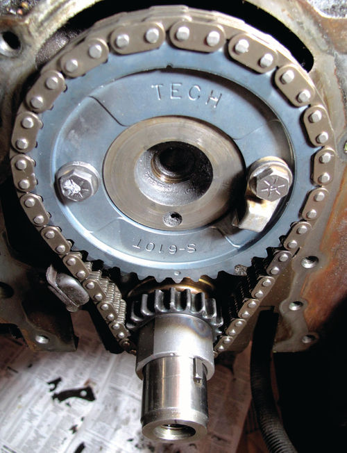
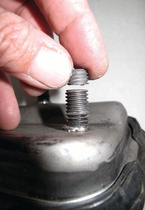
Even before I freed the timing cover, I saw signs that the timing gear was failing. Inside the oil pan, I spied a handful of yellow plastic pieces; broken teeth from the camshaft timing gear.
The stock timing gear is 95 percent aluminum; just the top half or two thirds of the teeth are plastic, designed that way, apparently, so the timing gear runs quietly. Where the plastic teeth had broken off—four in a row at one spot—stubby metal teeth remained (Photo 74).
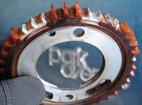
Were these stubs long enough to engage the old, loose metal timing chain? For the time being, yes, because the timing gear had been running on several bare teeth. The aluminum nubs were wearing quickly, however. Only when they stripped, as was inevitable, would the engine valves begin colliding with the pistons, thereby destroying the car’s engine.
By removing two bolts, I slipped the worn timing gear off the camshaft, taking the chain along with it. The crank gear, keyed to its shaft, slid off easily.
With the disassembly work done, I headed to my solvent tank to clean a variety of fasteners and other parts: the water pump’s very rusty mounting bolts, the alternator’s three mounting bolts and aluminum mounting bracket, the water pump pulley and its four mounting bolts, the oil pan bolts, the oil pan and the timing cover. I shined all the hardware at my floor-mounted wire-wheel buffer.
An Unexpected Search for New Parts
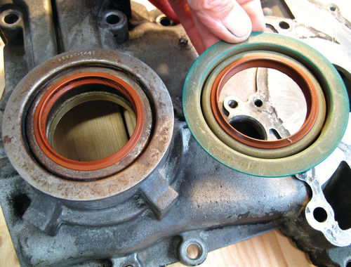
Next I pried the old crankshaft oil seal from the timing cover and tapped in a new one (Photo 75). I was surprised to find the engine’s oil pump hidden inside the timing cover. When the cover attaches to the front of the engine, the pump’s drive gear slides over the crankshaft, engaging flats that allow the crank to drive the oil pump.
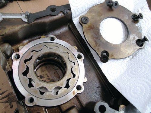
After inspecting and cleaning the gears, I reassembled the oil pump and called it good. If I had the chance again, I would renew the oil pump by installing an available $35 small-parts rebuild kit (Photo 76).
On the other hand, I was plenty busy collecting other last-minute parts. To avoid delays, I’d had all (or so I’d thought) necessary new parts standing by: a timing gear and chain set, a timing cover seal and gasket, and a new water pump and gasket.
Parkhurst’s water pump was an 11-year-old, 49,000-mile replacement. I opted to install a new one now, while it was so easy to do so.
I hadn’t expected to remove the oil pan, however, which proved necessary to free the stuck timing cover. That meant scrambling to find a new pan gasket.
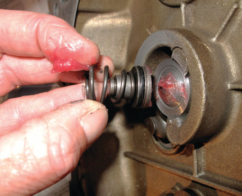
Likewise, only upon removing the cover did I discover damage to a spring-loaded camshaft thrust button. This item pushes the camshaft toward the back of the engine to limit its end play, apparently to keep its attached timing gear in perfect alignment with the timing chain (Photo 77).
I’d also waited until I’d uncovered the water pump to attempt to measure the diameter and lengths of the various heater and bypass hoses that needed replacing. It included straight hose, which I replaced from my own inventory, and molded hoses, which I ordered.
A Timing System Dexterity Test
I continued my cleaning at the front of the engine by using a long-handled scraper to remove all traces of gasket material from the timing cover’s mating surface.
I finished up by chucking a cylindrical wire brush into a right-angle cordless drill which fit into cramped quarters where a standard drill couldn’t go. With it, I cleaned all threaded holes in the front of the block, blowing out the scrapings with compressed air.
Before removing the old crank and cam gears, I’d slipped the vibration dampener back over the end of the crankshaft, using it as a wheel to turn the engine and align the timing marks on the two gears. These marks must align so the camshaft activates the valves at the proper time.
It’s customary to replace timing gears as a set, along with a new chain. Because the new timing chain was so tight, I devised a trick for installing the new gears. It’s a dexterity test.
First, press the crank gear on but don’t quite seat it. Next, hold the camshaft gear so its twin bolt holes align with the threaded holes in the camshaft flange.
Now, drape the top of the new chain over the camshaft timing gear and the bottom of the chain over the crankshaft drive gear. Press the timing gear over the camshaft flange. At this point, push a pair of aligning punches through the bolt holes in the new gear and into the threaded holes beyond.
While lifting the punches to stretch the chain, press inward on the gear. Pop, it’s on! Remove one punch from the cam gear to install its first attaching bolt. Remove the second punch to install the second bolt. Torque them. Seat the crank gear. Done (Photo 78).
Installing a Cover & Oil Pan
At a table I’d set up alongside the car, I attached the new water pump to the timing cover using its four small bolts. Four other bolts would do double-duty by securing both the pump and the timing cover.
Due to corrosion where the water pump attaches to the aluminum timing cover, I used red high-performance silicone sealer beneath the pump gasket.
I used clear silicone on both sides of the timing cover-to-block gasket and, furthermore, I coated the cover bolts with a Permatex thread sealer. Most, if not all, of these bolt ends contact antifreeze. My motto: No leaks. Not now, not ever!
The time had come to seat the bottom of the cover to the front of the engine. This I accomplished by carefully aligning the oil pump drive gear (on the underside of the cover) with the flats in the base of the crankshaft sprocket.
Something—what?—was preventing the cover from seating at the top. I soon discovered that it was interference with one of the cover’s two upper aligning pins. I’m assuming it was supposed to remain in the cover; it had rusted to the block, however, and stubbornly remained there. My attempts to pull it with Vise-Grip pliers made things worse by distorting it.
I could have drilled the cover’s aligning-pin hole very slightly oversize and things would have gone swimmingly. Shunning such a custom repair job, however, I elected to gently bump, bump, bump with the handle of my deadblow hammer until the cover eventually dropped into position.
All the while, my clear silicone was skinning over, which added some urgency to my manipulations. When I finally got the cover on, I spun the bolts in finger-tight as quickly as possible and then torqued everything to spec.
With similar care and speed, I reattached the oil pan—on which I used a silicone gasket sealer—and a variety of heater and bypass hoses. Eventually, I also reconnected wires I’d disconnected to gain access to vital parts and reinstalled everything else I’d removed to expose the front of the engine.
There. I hope I never see those timing gears again!
Living a Motor Mount Nightmare
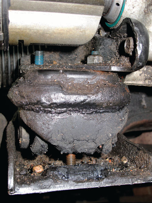
Because at least one of the car’s four metal-and-rubber motor mounts (which are filled with hydraulic fluid) had a tear in the rubber, I resolved to replace all four mounts. Even with the car on jack stands, I worked in tight quarters and ran into one difficulty after another (Photo 79).
I was flying blind, besides, as the factory shop manual made changing a motor mount sound tame: 1) remove mount’s two top nuts; 2) “raise engine slightly”; 3) remove mount’s two lower nuts; 4) remove the mount.
At the damaged right front mount, the first of the upper nuts came off easily. Two hours later, the second nut was still firmly attached. I, however, was becoming increasingly unhinged.
Despite removing three wires or wire harnesses in my path, I didn’t have the proper angle or side-to-side clearance to loosen the second nut with a wrench.
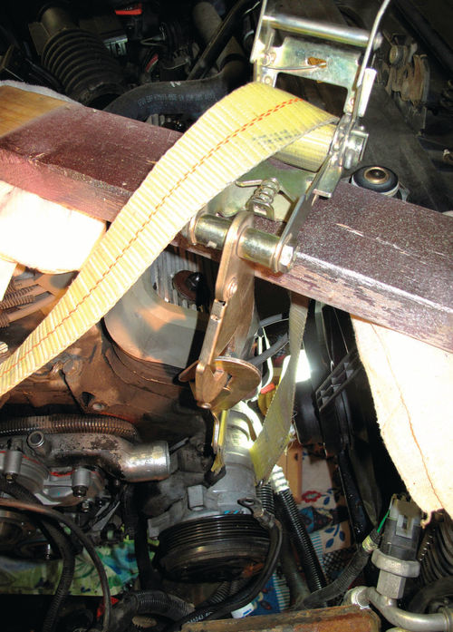
Accordingly, I removed three bolts holding the air conditioning compressor and looped a nylon strap around it and up over a 20-inch board—one end resting on the radiator, the other end on the intake manifold.
By this means, I winched the compressor upward 2 or 3 inches against the pressure of its flex hoses. It was enough to get a socket wrench on the previously untouchable nut (Photo 80).
I hoisted the engine as far as I dared. Employing a makeshift hoist, I winched the AC compressor upward two or three inches to gain access to a motor mount. Due to an overly long stud atop the new motor mount, I couldn’t lower the AC compressor far enough to install its rear mounting bolt. Using a cut-off wheel on a small drill, I shortened the motor mount studs to the proper length using the cherry picker hoist still attached to the engine for replacing the timing gears. Still the old mount remained wedged between the front frame crossmember and the mount bracket, which bolts to the engine block.
Ultimately, I used a long board to pry between the crossmember and the bracket, raising the right front corner of the engine just far enough to slip out the old mount. This was progress!
More Disassembly Required
The good times screeched to a halt after I’d spent 30 minutes trying in vain to install the new mount. A mounting bracket for the AC compressor—still suspended by a strap—was apparently interfering.
With difficulty, I removed four bolts holding the AC-mounting bracket. This allowed me to successfully install the new mount, reinstall the bracket, tighten all fasteners and then lower the AC compressor.
But now the compressor’s rear mounting hole was too high to align with a corresponding hole in the bracket. Why? A stud atop the new motor mount halted the compressor before I could lower it fully! (Photo 81).
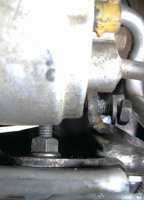
Accordingly, I winched the AC compressor out of harm’s way once again, disconnected its mounting bracket and removed the new mount. By measuring, I discovered that the new mount’s top studs were 15/16-inch tall. This was 3/16-inch taller than the factory studs and the cause of my ill fitting conundrum.
Once I shortened both top studs with a cut-off tool, I successfully installed the mount (Photo 82).
Three of the four engine mounts are, technically, transaxle mounts. At the left front transaxle mount, which was torn, two of the bolts holding it to the transaxle came out easily. Due to tight quarters, my socket wrench couldn’t reach the third bolt. Although I could reach it with a boxed-end 13mm wrench, I didn’t have enough leverage to crack it loose.
Winning the Battle of the Motor Mounts
Finally, after surrounding the bolt with heat shields cut from sheet-metal scraps, I heated the bolt head with my oxy-acetylene torch using a medium low flame.
Before it could cool, I placed the 13mm wrench back over it and placed a pipe at a 90-degree angle to the wrench’s free end. When I hammered on the pipe, the bolt popped loose. Despite a few more difficulties, I’d soon replaced the left front mount, leaving two more to go.
The left rear mount nearly finished me off, wedged as it is just below the steering gear and just ahead of the front sway bar. It took me several tries and about 90 minutes just to reach and remove one nut holding the mount to its mounting bracket.
I had to cut 1/4-inch from the new mount’s three lower studs and one upper mount-to-bracket stud. After this, it was easy as pie to push the new mount into place but impossible to position the mounting bracket afterward.
Thus I pulled out the mount, installed the bracket and then wrestled the mount back in, a difficulty because the bracket reduced the space I formerly had available. Replacing that single mount took 8 hours.
By contrast, the final mount, at the right rear corner of the engine transaxle unit, took an hour, which included cleaning up the hardware. Despite removing both the mount and its overhead mounting bracket, it was easy out, easy in all the way.
In our final installment it’s time to make the Buick shine inside and out and then go for a spin. But how can you even start toward the stated goal of rolling up 150,000 carefree miles in the “new” Buick when its engine intermittently cuts out…first in parking lots and then in traffic.


