
OVERHAULING THE LAST OF THE QUADRAJET CARBURETORS PT. 7
This Time We’ll Install Plugs In the Fuel Bowl and Then Start Some Reassembly Work.
Installing Plugs
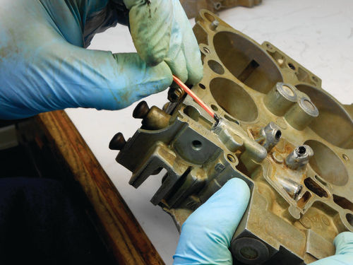
While I was mixing the epoxy, Photo 145 shows my wife Mary warming up the fuel bowl with a heat gun in preparation for applying the mix. In this direction the heat gun is actually shooting hot air through the open fuel passages and out the bottom where the plugs will be replaced. A new toothpick was used to wipe a small amount of the mixture into the threads as seen in Photo 146. With the plug inserted on the Allen wrench, it’s also coated with the Marine-Tex as you see in Photo 147.
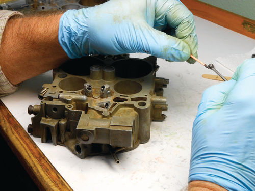
Finally, the plugs are all threaded into place as shown in Photo 148. Around the edge of the plugs, epoxy was smoothed off to form a fillet as seen in Photo 149.
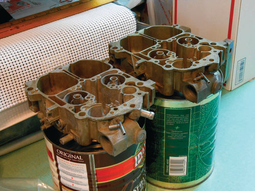
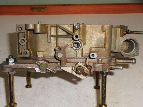
The procedure for the two large plugs on the swap meet carburetor is identical. The instructions state that this stuff won’t sag, but to be on the safe side, both fuel bowls were then turned upright and positioned on a couple of old cans as shown in Photo 150. This should help eliminate the epoxy traveling deeper into fuel passages, and keep it where it was applied. The instructions say it sands easily, but that shouldn’t be necessary. While they do say to use the product in a well-ventilated area, there is very little odor to it.
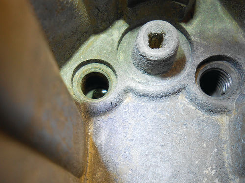
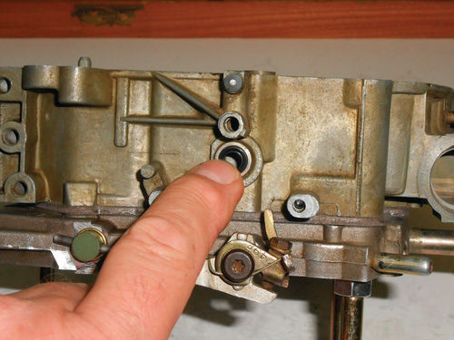
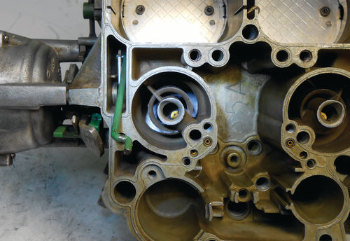
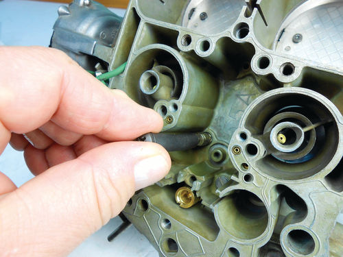
The only complication experienced was that some of the epoxy traveled into the primary fuel wells. Take a look at Photo 151 and you can see the worst offender on the swap meet fuel bowl. One of the jets and metering rods were temporarily threaded into each location to make sure the metering rod freely traveled its full length. All but the one in Photo 151 did. Using a sharpened pick tool and by tapping it with a hammer, the epoxy was chipped away until the metering rod traveled its full length. The Dremel tool was also ready to go if needed with a flexible extension shaft and a very small “ball shaped” carbide cutter that would allow it to get into tight areas like this. This tiny cutter could easily sneak past the threads avoiding any possibility of damaging them. This issue was most likely a by-product of applying epoxy to both the plug and internal threads. Doing this was my choice, and was not suggested in the instructions that came with the plug kit. I was certainly aware this could happen, but had thought the small amount that was wiped into the freshly cut threads wouldn’t be a problem. Correcting the mishap in one out of four of the wells was not a big deal, probably taking about 10 minutes to chip and thoroughly clean out the area. Possibly positioning the fuel bowl differently during the curing time might be the answer.
If it were to be done again, the front of the fuel bowls (fuel inlet side) would be set facing down. So yes, I would do it the same way again. If in the future another Quadrajet needs this bottom plug repair, the threading of the small holes would stop at three full turns. One less thread would certainly keep that plug farther from the accelerator pump discharge passage that we spoke about (reference Photo 142 in the May issue). This passage was checked again with both compressed air and carburetor cleaner and was still flowing freely.
Time To Start Putting Some Things Back Together
There is no right or wrong order in which things must be replaced. Of course that’s only partially true; for example you wouldn’t replace the float before attaching the new needle and having the seat installed. And you must install the jets before the metering rods. So common sense can be applied to this.
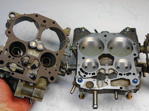
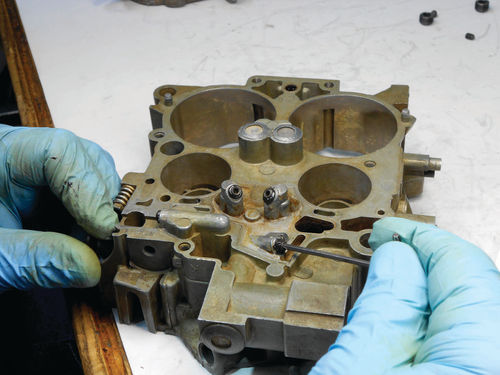
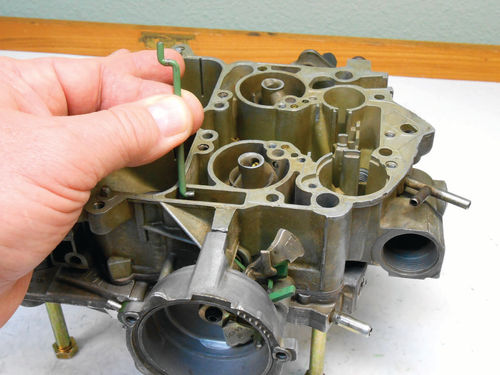
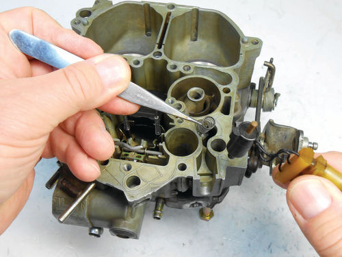
With the mating surfaces of both the fuel bowl and throttle body perfectly clean, they can be reassembled. Photo 152 shows the new gasket is positioned on the two guide pins of the fuel bowl and they are secured together here in Photo 153 with three throttle body screws. The choke shaft seal is positioned with the lip facing out, and then pushed in with fingertip pressure as seen in Photo 154. Then Photo 155 shows the secondary lockout lever positioned on its boss. It’s time to replace the choke housing while engaging it with the choke lever. The housing perches on three points, and the indexing notch for the thermostat faces forward. Before getting started, study how the lever will be positioned on the shaft of the housing. You can go back to when we removed the choke housing and review Photo 43 or just note the position of the flats on the choke shaft. Once you know its approximate angle, it’s not difficult.
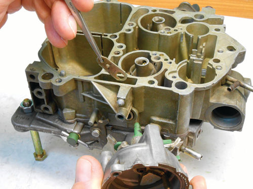
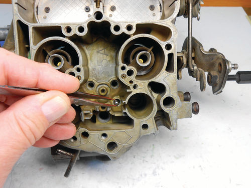
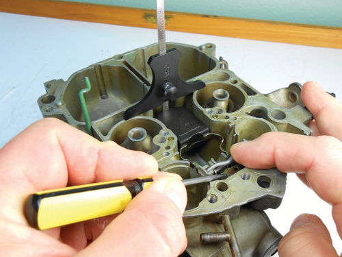
In Photo 156 a pair of tweezers is used to lower and manipulate the choke lever down into the cavity. The choke housing shaft is fed in through the new seal while the lever is positioned over it. At the same time the throttle shaft will need to be opened slightly to be able to completely seat the choke housing to the fuel bowl. It should be resting on the perches, and as you move the fast idle cam the choke lever (now inside the cavity) should move with it and not bind. The center retaining screw is replaced and the choke housing is secured tightly in place. To engage the choke rod with the lever, start with the rod positioned as shown in Photo 157. While looking down into the cavity, lower the rod until it’s in line with the hole at the end of the lever, and then rotate it 90° clockwise to engage it. Photo 158 shows what you should be looking at. For now the choke thermostat will remain out, as the choke stat lever adjustment will need to be made with it removed.
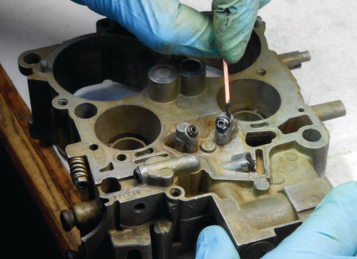
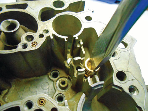
Now let’s move to the discharge ball. But before installing the new one, find the old one that was removed and saved. As long as it appears free of damage or pitting, it can be cleaned and used to re-stake the discharge ball seat. If it’s not in perfect condition, skip this step. The discharge ball fits into the threaded hole located in the raised step of the fuel bowl, next to the accelerator pump well. Everything should be perfectly clean, but re-check to make certain there is no debris down in the hole where the discharge ball will be placed. If there is any question, use compressed air or a bit of carburetor spray to clear it.
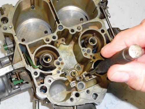
Now drop the clean old ball into the hole as shown in Photo 159. With a 5 ⁄32" drift pin placed on top of the ball as seen in Photo 160, strike it gently with a small hammer, “Tap- TapTap.” This reforms the seat if there is any distortion. This tip was passed on by Marion Hardman, an AC Delco instructor at the Atlanta, Georgia, GM training center many decades ago.
To remove the old ball, tip the bowl upside down and it should fall out. If it’s stubborn, tap the fuel bowl on the edge of a wooden work bench or something similar to dislodge it.
In Photo 161 the new discharge ball has already been dropped in, and the ball retainer is tightened. Normally the jets and metering rods would be installed at this point, but to avoid added distractions in the photos, the float adjustment will be performed first. The new needle seat with gasket is replaced in Photo 162. A new float came in the kit from Cliff’s High Performance, and out of curiosity its weight was checked on a sensitive pennyweight scale and weighed in at just under 5 pennyweights. (For reference a pennyweight = 1.555 grams and 28.349 grams = 1 ounce.)
This was slightly lighter than the one that was removed, so that eliminated any possible thoughts about reusing the old float. A quick test to see if the float pontoon is starting to saturate with fuel is to squeeze it between your fingers using your fingernails to apply pressure. If any moisture releases, replace the float. Unsure? Replace it anyway.
With the needle pull clip hooked off the inside of the float arm (opposite from the side it was on when removed), the new float, needle and hinge pin are lowered into position. To correctly measure the float height, the measurement is taken 3 ⁄16" in from the end of the float. This float had a line on it to indicate where to take the measurement.
In Photo 163 the float height is being checked while the pick tool is being used to apply just enough pressure to seat the needle, and my index finger is holding the hinge pin down. If you don’t hold the hinge pin, the adjustment will be incorrect. The specification for this application is 11⁄32" below the surface of the fuel bowl. Should the float be too high, it can be corrected without removing it. Tilt the float on its hinge pin to raise the needle off its seat; this is to avoid damaging it. While holding the rear of the float frame with a fingertip, push down gently on the end of the pontoon. It doesn’t take much pressure, so do a little at a time and recheck the measurement. Should the float be too low, lift it out of the fuel bowl, and while holding the end frame, lift upward on the end of the pontoon. Photo 164 points to the area that allows for this movement.
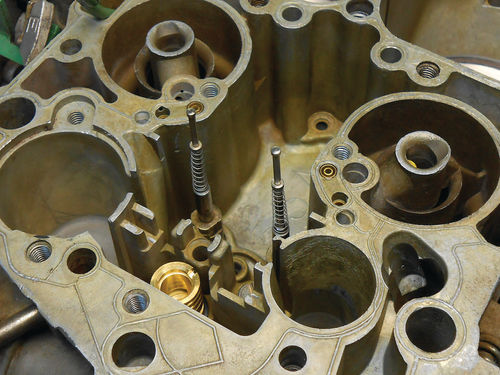
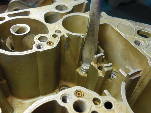
Once the adjustment is correct, the float is temporarily removed to allow the jets to be replaced and tightened. Photo 165 shows a small piece of vacuum hose is handy to start the threads on the jets. The jets are then tightened, and the metering rods with their new springs are dropped into their guides in Photo 166. The metering rods will be removed for making the MC (mixture control) solenoid lean adjustment, but now is the best opportunity to get a good view of the assemblies.
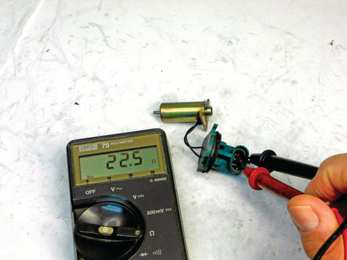
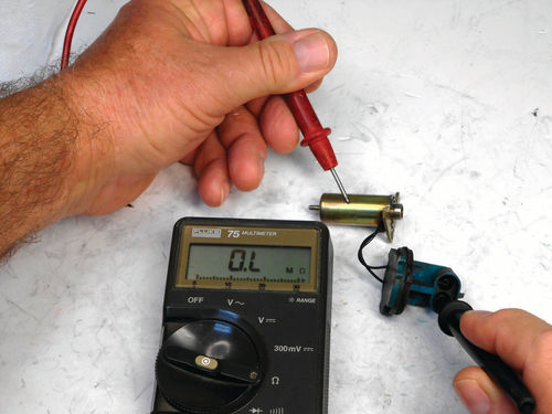
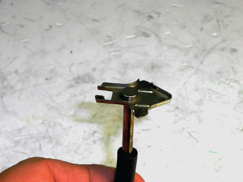
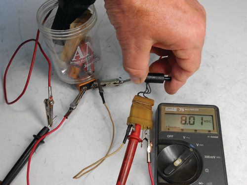
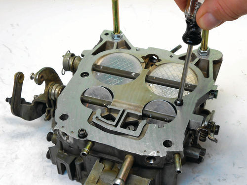
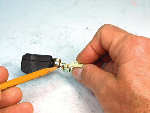
There are several components that need to be tested and visually inspected before reusing them. In Photo 167 the MC solenoid is measured for resistance. Probing each terminal, the reading should be between 20- 26 ohms; this one reads 22.5 ohms. Checking for an unwanted ground, one probe is touched to the solenoid housing, while the other is inserted into each of the electrical terminals as shown in Photo 168. Both these terminal checks should register infinity or overload on the gauge. Visually inspect the wires for any breaks and worn insulation, and give a look at the terminals to make certain they look healthy. It’s no surprise that the solenoid from the swap meet carburetor failed the resistance test, reading infinity. Take a moment to look at the solenoid plunger shown in Photo 169. Inspect for scoring of the plunger itself, and that it moves freely within the solenoid. Inspect the “paddles” that depress the metering rods to make sure they are not bent or otherwise damaged. The TPS (throttle positioning sensor) switch normally receives a 5-volt signal from the computer to the top terminal (A) in the connector. The bottom terminal (C) is ground; and the center terminal (B) feeds back a voltage signal to the ECM (engine control module) that translates to the throttle’s position. In Photo 170 a 9V battery was used for the test, as the plunger (under my thumb) was moved through the full range and then back and forth to verify smooth operation. The wires and insulation all looked fine, so after first dropping in the spring in Photo 171, the TPS switch is placed in its cavity. Had the TPS required replacement; the adjustment would most definitely need to be checked. However after an overhaul it’s a good idea to verify it anyway. There is also an access plug that will need to be removed, and we will explore that when returning to the air horn. They stress the importance of this adjustment, and it will be covered once the carburetor is reinstalled on the vehicle.
The flat secondary bore air baffle is slid back into position, so the installation and adjustment of the mixture control solenoid will be next. That will involve using a special gauging tool that will need to be made first. Before that, let’s review the additional items that have been purchased.
Additional Parts… Sources and Costs
The Caprice only required a set of metering rod springs, but the list was longer for the swap meet carburetor.
Below is the total list:
• Pair of metering rod springs (#CUD521) – $4.95 per pair (both carburetors need them, so x 2)
• Pair of idle mixture screws 4m x .50 x 1.2660 (#CUD35487) – $9.95
• MC solenoid; New (#MCS-1) – $59.95 (a rebuilt was available for about half this price).
• Choke pull off- (#PO-5080LC) – $19.49
• TPS switch (#TPS-1) – $19.95 All ofthese parts were ordered from Carbs Unlimited at www.carburetion.com; . They offered both new and reconditioned MC solenoids, where others only offered the reconditioned. A TPS switch was added to the list mainly because I was having trouble convincing myself the one in the swap meet carburetor was actually good. But as it turned out, it was fine. The fact that it resides in its own separate bore and not down in the fuel bowl kept it from being subject to the moisture that killed the MC solenoid.
An assortment of screws for throttle valves were ordered from Mike’s Carburetor parts at www.carburetor-parts.com. Mike’s also has a Tech Department offeringaccess to tons of free PDF downloads of carburetor information and much more. I downloaded the 38-page April 1981 Delco manual on E4ME & E4MC Quadrajet. This is great information to have when overhauling or adjusting this carburetor. Most of this information is likely in the factory service manual, but if there is one small detail or a better image showing something, it could be a lifesaver. Go to their web page and click on “Technical” in the top right corner to see their total offerings. A search for Quadrajet parts online will show many additional suppliers to choose from, but not all have parts for CCC carburetors.


