
OVERHAULING THE LAST OF THE QUADRAJET CARBURETORS PT. 10
It’s Time to Do Some Reassembly Work and Make Some Adjustments In the Process.
Reassembling the Carburetor
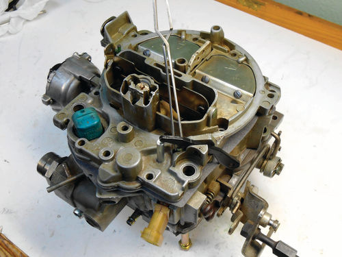
Photo 218 shows the air horn gasket in position or close to it. The accelerator pump return spring is causing the front corner to lift. You would also see the plunger for the TPS if the gasket were flat.
When replacing the air horn you are aligning the secondary and accelerator well tubes, the connector and rubber seal for the MC solenoid, accelerator pump shaft, TPS actuating pin, TPS adjusting lever and the choke rod.
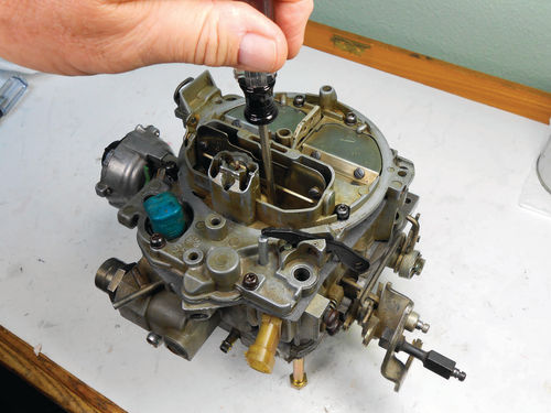
If desired, the choke rod can be removed and reinstalled with the air horn on. Even though the smaller hole in the air horn reduces visibility, it takes little effort to line up the lower end of the choke rod, and it’s one less obstacle to work around. If you do remove it, pushing down the fast idle cam will raise that lower choke lever and make rod installation easier. Photo 219 points to the TPS lever we spoke about earlier. During installation it will need to be pushed upward into the air horn.
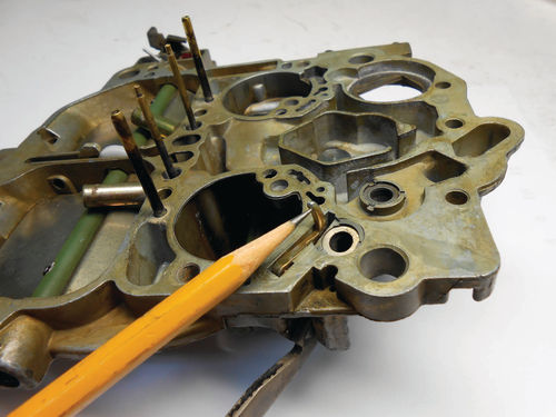
Photo 220 shows the air horn tightening sequence. I enlisted the help of my wife to hold down the corner of the gasket and help guide while the air horn was manipulated to line things up. As it turned out it seemed easier to fit the rubber solenoid connector seal into the air horn as opposed to around the connector, but that might just be me.
Not wanting to take a chance of the TPS actuating pin falling out at the last moment, locking tweezers were used to secure it in Photo 221. Don’t try to force the air horn or you risk breaking something.
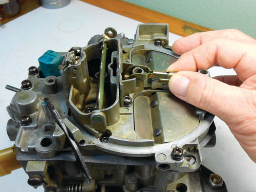
The TPS and its adjusting lever was another obstacle. A small screwdriver was used to lift up the lever and finally the cover dropped in place. With the air horn screws started; the tightening sequence begins below the choke valve as shown in Photo 222. The air baffle is installed along with screw #3 and #4 here in Photo 223. The secondary metering rods and their holder are aligned in Photo 224. The attaching screw fits into the hole between my thumb and index finger and is tightened with a T-8 bit. The pump rod is reconnected and secured with the small retaining clip as shown in Photo 225.


Photo 226 shows the choke valve lever has been placed on the rod and its retaining screw replaced in Photo 227. There are still several things to replace like the vacuum break and its air valve rod, choke thermostat, and even the ISS, but a couple of these must be off to allow checking some of the external adjustments, so we will come back to them in a bit.
External Adjustments A. The Mixture Solenoid Rich Mixture Adjustment
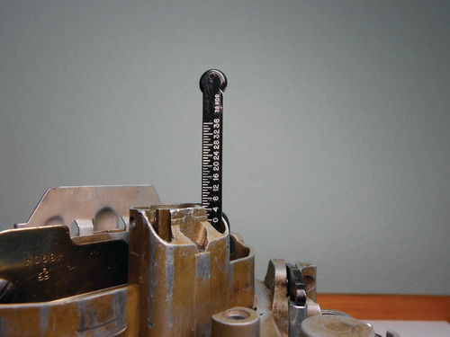
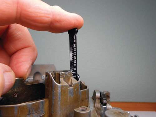
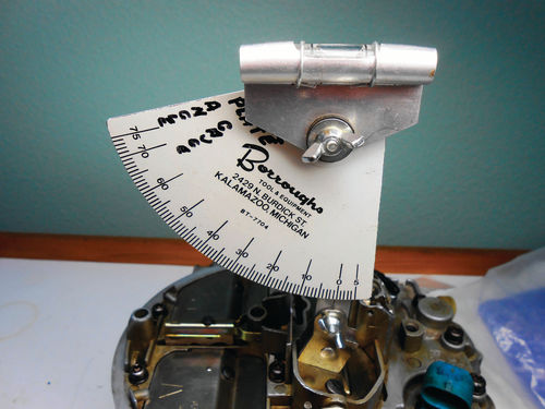
This can be checked using the plastic float gauge we referenced earlier, or a narrow (1 ⁄4” wide) scale like that used on the Starrett depth gauge. Insert the gauge through the air horn vent hole as shown in Photo 228. It can be inserted through either of the two opposite holes, and the reading is taken at eye level against the edge of the air horn. This is reading 5 ⁄32”. In Photo 229 the gauge is pushed down, depressing the solenoid plunger. Note the reading again at eye level. This time it’s 9 ⁄32”, so the total travel is 4 ⁄32”. The manual states it should be between 3 ⁄32” – 5 ⁄32” with the desired setting at 4 ⁄32”. So this is perfect and no further adjustment is necessary. That initial pre-adjustment of ¼ turn off the seat made back when removing the access plugs set it up nicely. That’s not always the case though as the swap meet carburetor still needed more adjusting.
B. The Choke Stat Lever Adjustment
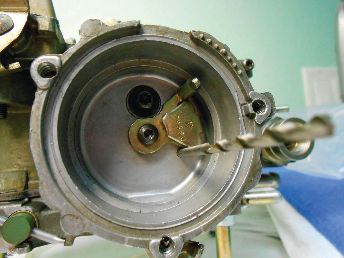
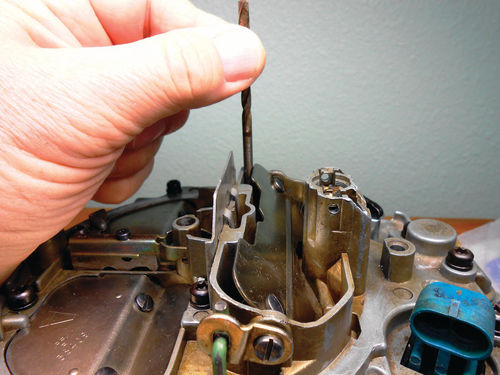
You need a .120” plug gauge or a #31 drill for this check. Open the throttle and raise the fast idle cam all the way up onto the high step. With the choke thermostat removed, push the choke stat lever up to close the choke valve. To check the lever for correct orientation place the .120” gauge in the hole seen in Photo 230. The gauge should fit in the hole and touch the lever. If adjustment is necessary the choke rod should be bent slightly just below where it connects to the choke valve lever as pointed to in Photo 231. While this one was fine, the drill bit wouldn’t fit into the hole on the swap meet carburetor. The rod needed to be lengthened so Vise Grips were used to straighten a minor bend. When finished, replace the choke thermostat. It has a square loop at the end, and it fits over and captures the stat lever. Once in position rotate it until the notch lines up with the indexing boss on the housing and the thermostat sits in the recess. Replace using the three screws (or rivets) and retaining ears. Screws seem the logical choice, in the always possible event the thermostat might need to be removed again.
Using the choke valve angle gauge— Adjustments relating to the position of the choke valve are measured with an angle gauge and the manual only gives the value in degrees, but you have an option. There is a conversion chart from angle degrees to decimals included in this series that allows you to use either a carburetor gauge pin set or drill bits to do the job.
GM considers the angle gauge the most accurate and desired method of checking these adjustments, and these gauges are readily available starting from about $35 on eBay and many other sources. First make sure the carburetor is either on a carburetor stand or the “bolt stand” we’ve been using. Naturally it must remain stationary during this procedure.
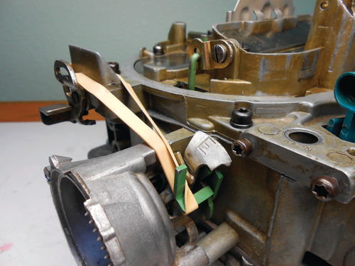
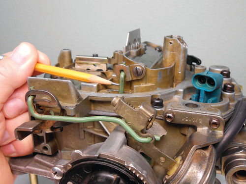
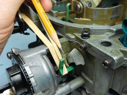
1. Attach a rubber band to the vacuum break lever (the green tang) of the intermediate choke shaft as shown in Photo 232.
2. Open the throttle to allow the choke to close.
3. Attach the angle gauge magnet to the closed choke valve, and then rotate the degree scale until zero is opposite the reference line.
4. Without disturbing the degree scale, rotate the bubble until it’s centered in the vial. Here’s what it should look like in Photo 233.
5. Set the angle gauge to the desired setting and perform the specific instructions for that check. There are only three adjustments to check using the angle gauge, so rechecking an adjustment once or twice is a good practice and will help avoid errors.
Using Gauge Pins Or Drill Bits as a Measuring Option
The measurements are all taken between the upper edge of the choke valve and the wall of the air horn as seen in Photo 234. If you’re working with drill bits this may require using number, letter and even fractional drill bits. In some cases you may still have to compromise if using drill bits to measure, because there may not be a bit the exact size.
C. Choke Link—Fast Idle Cam Adjustment


Desired setting for this is 20° (+ - 2.5°). If performing this adjustment with pin gauges or drill bits, a .110” or #35 drill bit is the desired fit. The acceptable range is from @.093” (#42) - .126” ( 1 ⁄8” drill bit). After completing steps 1 through 5 and setting the angle gauge to 20°, the manual says to place the fast idle cam on the second step against the cam follower lever, with the lever contacting the rise of the high step. In other words, come down off the high step, and then back up against the edge of the high step. If the lever doesn’t contact the cam, turn the fast idle adjuster screw until it does. If the bubble is centered, it’s at the desired setting. If not, move the angle gauge to center it and see if the reading is within the range as was done in Photo 235. This is reading 19° so we’re good.
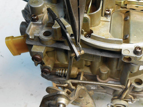
Had it been out of tolerance, adjustment is made by bending the fast idle kick lever (between the green vacuum break lever and fast idle cam) pointed to in Photo 236. Using pliers, bend it in the direction necessary.
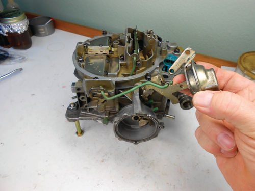
The vacuum break had not been installed to make this check easier to see, so let’s complete that now. The air valve rod is connected to the air valve lever and vacuum break in Photo 237, and then it’s secured to the side of the air horn with two screws as seen in Photo 238.
Next, we’ll continue with our reassembly and adjustments.


