
OVERHAULING THE LAST OF THE QUADRAJET CARBURETORS PT. 9
We’ll Be Installing and Adjusting Parts, and Once Again See the Value of Having a Series of Project Photos.
Editor’s note:When we last visited with John and his carburetor project in the November issue, he was working with some seals prior to returning the air horn to the fuel bowl. We’ll pick up with him there.
Make sure to verify what’s in your carburetor kit before removing the old seals. Open up the small packets on a clean surface and spread out the contents. After all is inventoried use one of those snack-sized Ziploc bags to seal the items up again. I ended up with two additional choke housing seals, and these small green seals that honestly aren’t worth the effort of replacing due to their fit. The pump shaft seals, however, fit nicely.
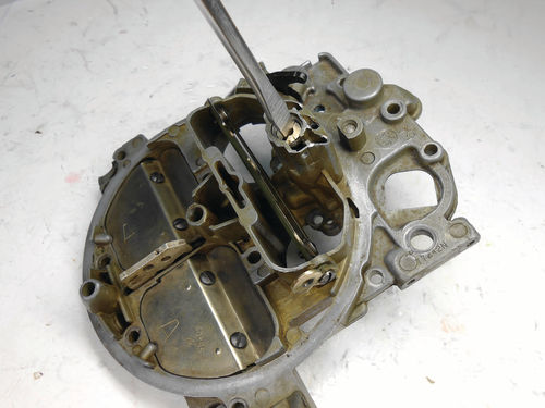
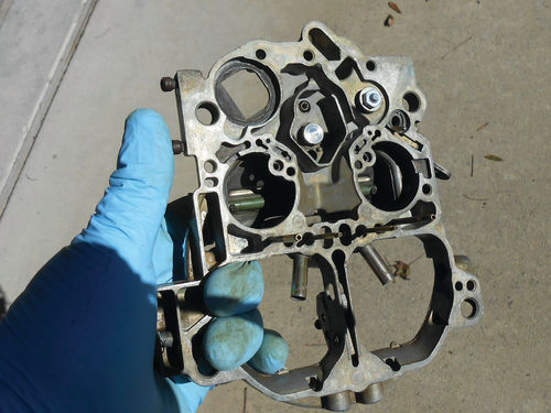
Note that lever protruding downward next to the throttle position sensor (TPS) actuator seal visible in several images. This is the TPS adjustment lever. It adjusts the TPS by determining how deep it sits in the bore. If the TPS needs to be adjusted; the special tool is inserted through the access hole (see Photo 187 in the November issue) and rotated. This in turn moves the lever and it either pushes the TPS deeper into its well which reduces the voltage, or allows the spring pressure to lift it up until increasing the voltage.
The Value of Taking Pictures…
It’s time to install those accelerator well tubes that were found loose in the bowl. They press in only about 1 ⁄8”, so the ends are scuffed with some 600-grit sandpaper and a dot of red Loctite applied as shown in Photo 193.
In Photo 194 the first of the two tubes is tapped in place using a plastic-capped hammer. This takes little effort and the job is quickly completed.

You may have noticed in the photos that the Idle Air Bleed Valve (IABV) has been removed. Remember the top of the valve was grazed early in the project with the drill bit when removing the metal cover plate? It was removed when cleaning the air horn, but I neglected to make reference of its depth by counting how many turns it took to bottom it. This isn’t suggested in the manual, but when the gauges are impossible to locate, it would be a good idea. The next best thing is to reference our swap meet carburetor. It hadn’t been disturbed so the number of turns could be counted. This will possibly get the adjustment within the hemisphere at best, and then the gauge that will be made should get it closer until the final adjustment is made on the vehicle.
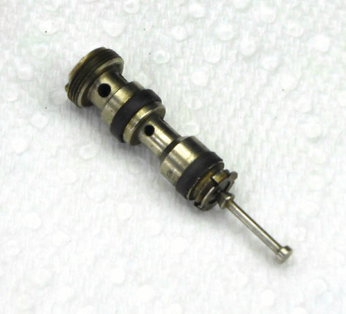
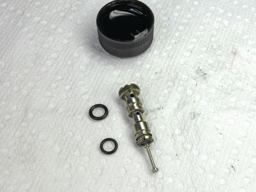
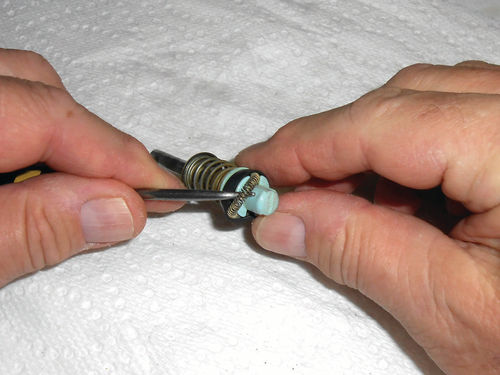
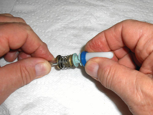
Here is the removed IABV in Photo 195. The two flattened out O-rings will be peeled off, and the valve cleaned. It was cleaned with some carburetor cleaner, and then soaked in a container of Acetone. The O-rings are not identical, as can be seen in Photo 196. The top one is thicker, but regardless they will both be coated with transmission fluid and rolled up from the bottom and into their grooves. A tiny screwdriver is helpful in encouraging the O-rings on, over and into their grooves. The valve is ready to install in the air horn, and with the information gained from the swap meet carburetor, it was initially threaded in 73 ⁄4 turns as shown in Photo 197.
An interesting side note. When sorting through some of the extra unneeded images made during this project, there was one that had a clear, close view showing the IABV still installed in the air horn. The unusual grazing mark created by the accidental contact of the drill bit pinpointed its exact orientation just like hands on a clock. And the number of threads above the valve were clearly visible. So how did it match up with the guesstimated adjustment? Unbelievably, it was exact…wow. Here is a good case in point with regard to the value of photos you don’t think you will ever need.
What remains in the carburetor kits, and what’s next? Of course there are the extra seals that don’t fit anything; the gaskets, accelerator pump, fuel filter with spring, and with Cliff’s kit there is a replacement spring for the secondary air doors, and new secondary metering rod cam.
Completing the Fuel Bowl

Just a few things will finish up the fuel bowl. The fuel filter with spring and the rear adapter fitting for the brake booster can now be threaded in place. In Photo 198 the accelerator well baffle is slid in place, and in Photo 199 the accelerator pump and return spring are positioned.


As you might imagine this is quite springy, standing up well above the top of the fuel bowl. So the gasket will remain off until the air horn is ready to be replaced. If you are using the Standard Hygrade carburetor kit there are a few additional steps. The original accelerator pump assembly is completely reused; only the pump cup and garter spring are replaced. Usually this is not a problem as long as the pump is in good shape. The moisture that was in the fuel bowl of the swap meet carburetor wasn’t kind to the pump. If there were no other option it could be used, but the fact that the old one from the Caprice was replaced in its entirety is ideal. Photo 200 shows using a pick tool to remove the old garter spring. Next it’s the cup’s turn as seen in Photo 201. The groove for the pump cup is cleaned with a Q-tip, and then the lubricated cup is slid on using the included guide as shown in Photo 202. Take a look at Photo 203, which shows the cup fully installed. The garter spring is then manipulated around the pump tip until it’s positioned under the pump cup. Now this pump is complete.
Replacing and Adjusting the Air Valve Return Spring
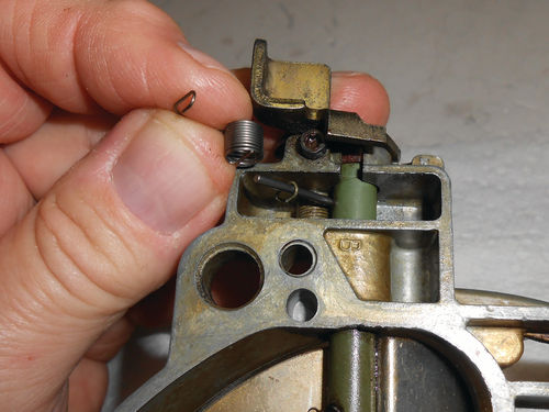
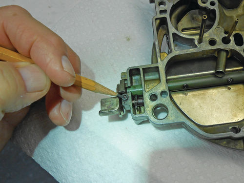
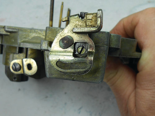
Photo 204 shows the new spring from the kit, and where it will be going on the Caprice’s air horn. Regardless if you are replacing or just adjusting the air valve spring you will need to loosen the set screw pointed to in Photo 205. This requires a Torx T-10 bit, and it’s beneficial to actually remove it because this allows you to squirt some penetrating oil into its hole.
What appears like a screw head in the square cutout of the air valve lever in Photo 206 is actually the adjusting pin. It’s not threaded and both ends are identically slotted and knurled. This one was stiff, but once it was worked back and forth a few times it loosened up.
When only adjusting the air valves, here is the procedure. If the air horn is removed from the carburetor as is the case here, position it top side up as it would normally be sitting on the carburetor. Rotate the adjusting pin counterclockwise until the air valves start opening, and then back up the adjuster until the valves just close. Repeat this several times to verify the location is correct and mark the pin’s location. Now the air horn can be re-positioned so that it’s more comfortable to work on. This is usually standing it on its side with the adjusting pin facing up. If the adjusting pin moved, line it up again with the reference mark and then load the spring with the additional turn listed in your manual. For this carburetor that is an extra 7 ⁄8 of a turn. While holding the adjusting pin at this “loaded” position, use the T-10 bit to tighten the set screw, but don’t overdo it. The manual recommends applying lithium grease where the spring captures and slides on the air valve fulcrum pin. If the spring is removed for any reason, some grease can also be applied inside its coils. That completes the adjustment.

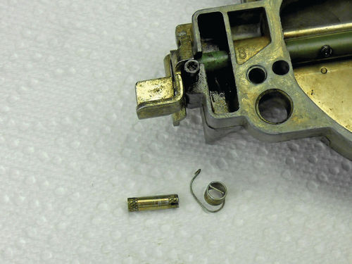
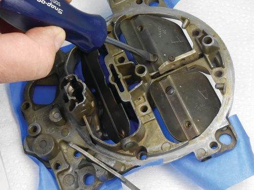
To remove the adjusting pin and replace the spring, start by rotating the adjusting pin back and forth slightly searching for the point of least friction. This should make the pin easier to slide out. A sharpened pick tool is then used to probe between the inside edge of the spring and casting, in an attempt to work the pin out as is being done in Photo 207. Once the head of the pin starts to protrude out, needle nose pliers can be used to pull it straight out. Photo 208 shows the removed pin and old spring. A Q-tip works well for applying lithium grease inside the new spring’s coils, and then it’s positioned in the cavity so that it’s able to capture the air valve fulcrum pin. The adjusting pin is then reinserted into its hole while the pick tool is used to position the spring so the pin passes through it. When the pin is fully into the coils of the spring, rotate it until the tang of the spring lines up with the slot in the pin, and then it can then be fully installed. From here follow the adjusting procedure outlined above.
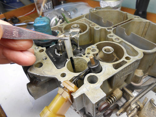
Secondary Metering Rod Eccentric
This time the swap meet carburetor is the subject. The metering rod cam is on the air valve shaft in between the air valves as pointed to in Photo 209. That’s the replacement I’m holding. To replace it, both air valves will need to be removed; the return spring released, and the shaft partially slid out to access and slide off the cam. This is similar to removing the throttle valves when installing the shaft bushings.
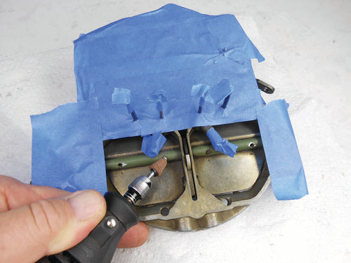
As with the throttle valves, scribe around the screw heads to leave a reference mark on the top of the valve to ease re-installation. These air valves are bore specific, and will only fit one way. The ends of the screw threads must be ground flush to the air valve shaft as is being done in Photo 210. The masking tape is an attempt to stop most of the abrasive dust from getting into the air horn. The screws are then removed as seen in Photo 211, and the valves are lifted (or fall) out.
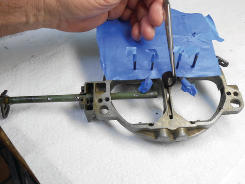
The shaft is now free to slide out, and that’s just what’s done. In Photo 212 the old cam was grabbed with tweezers as the shaft was removed. Once wiped off and the tape removed, the air horn and valve shaft were sprayed with cleaner and then washed in hot water and Dawn detergent. To help avoid carburetor cleaner reaching the rubber pump plunger seal, a bolt and nut were used to plug the passage as shown in Photo 213. There was no easy solution for the smaller TPS seal due to its location and the pump lever. So when spraying with cleaner the air horn was held with my thumb blocking it, and the spray was never concentrated in that area.

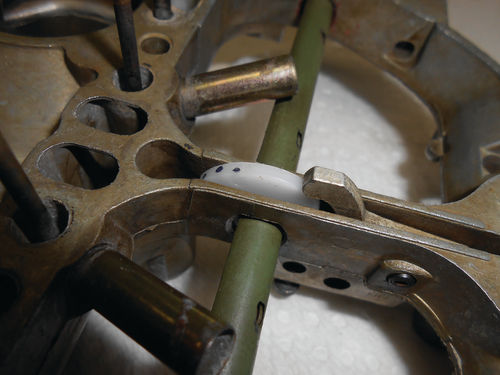
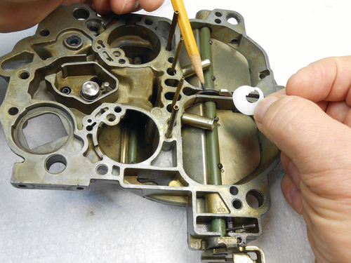
Photo 214 shows the air horn from the Caprice to the right as a comparison aid, and behind it the air valve shaft in the same orientation with one valve in place followed by the old cam. This cam can be accidentally installed rotated 180°, so pay attention. The pencil point is referencing the thinnest point of the cam, located at the high edge of the air valve shaft. This is the correct position. When removing or installing the new cam, it doesn’t hurt to make reference marks that tell you the orientation is correct, like you see in Photo 215. When the old cam was removed it was discovered to have a break in it. Coincidentally it’s in the same area the pencil was pointing to in Photo 214 and it goes completely through down to the shaft. This wasn’t seen due to its location until it was removed. At some point that old cam could have broken off the shaft. To complete the service the valves are replaced and the new screws provided with the cam were coated with Loctite sealant. From all the cleaning any lubrication that was on the tension spring was removed, so it was re-lubricated. The area to concentrate on is where the spring rides on the fulcrum pin.
Checking the Pump System

The manual says “fill the empty float chamber and pump well with a clean solvent such as mineral spirits.” I chose to use Naphtha, a fast-evaporating solvent that leaves no residue and is safe on plastics. It was poured directly into the pump well until there was enough to perform the test. Next use two fingertips to plug the two pump discharge passages. The pencil is pointing out one of the two in Photo 216; the other is on the opposite side. With the other hand push the pump assembly down slowly. The pump assembly should not travel to the bottom of the well. “The only movement should be the compression of the duration spring. If pump assembly moves down in well, this may indicate that the pump cup is not sealing properly, the pump well is worn or scored, or the pump discharge ball is leaking (as indicated by bubbles around the plug).”
In this test all appears to be good. The second check requires some additional Naphtha to be added into the pump well, and then push down on the pump assembly until solvent starts to discharge slightly from those same discharge passages. The fluid should remain level at the top of the two passages. Remove the pump assembly and continue to watch. “If level begins to drop, the discharge check ball may be missing, or may not be seating correctly because of foreign material, damage to the ball, or because the seat for the ball needs re-staking.” While it would be unlikely to forget the check ball during reassembly, it isn’t impossible. Most likely some contaminant could be stuck to the ball or remained in the seat. This also checked out OK.
Next, we’ll start to reassemble the carburetor.


