Rebuilding a 4-Speed Hydra-Matic, Pt. 2
It’s Time to Inspect and Service the Transmission’s Subassemblies. Join Us as We Start at the Front and Work Toward the Back.
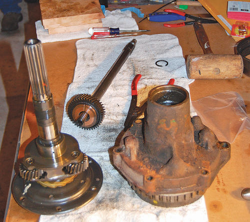
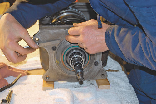
AFTER REMOVING THE four-speed Hydra-Matic case from our 1953 Pontiac Catalina and disassembling the parts inside it, it’s time to start servicing the 16 units or sub-assemblies that make up the transmission.
Depending upon the amount of work needed, Fatsco Transmission Parts in Pine Brook, New Jersey, can supply a Master Kit, Major Kit, Overhaul Kit or Seal-Up Kit.
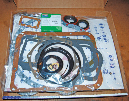
The Hydra-Matic Master Kit includes: all gaskets, all rubber O-rings, all lip seals, front and rear metal clad seals, a complete sealing ring set, 12 original-type waved (half cork/half paper) friction clutch discs and 12 steel clutch plates. The kits now include Hydra-Matic “second design” lip seals so you no longer need to use the brass expander rings under the seals (although the kit we installed awhile ago included these). We also ordered new front and rear bands.
The kit you order should be correct for the year of the car. Between the ’40s and ’50s, many refinements were made to Hydra-Matic transmissions. However, except for the location of the front pump and the change to a cone clutch, the engineering improvements did not affect servicing procedures.
The units or assemblies you’ll find yourself dealing with are:
1. Front planetary assembly
2. Rear planetary assembly
3. Front band
4. Rear band
5. Front servo
6. Rear servo
7. Front oil pump
8. Rear oil pump
9. Governor
10. Pressure regulator valve
11. Oil delivery sleeve
12. Reverse planetary assembly
13. Torus members
14. Main shaft
15. Output shaft
16. Control valve assembly
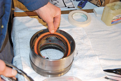
Servicing the Front Planetary Assembly
This consists of planetary gears, clutch, clutch pressure plate and either a ring-type hydraulic piston or (in 1940- ’42 models) two pistons. This assembly is located at the front of the transmission.
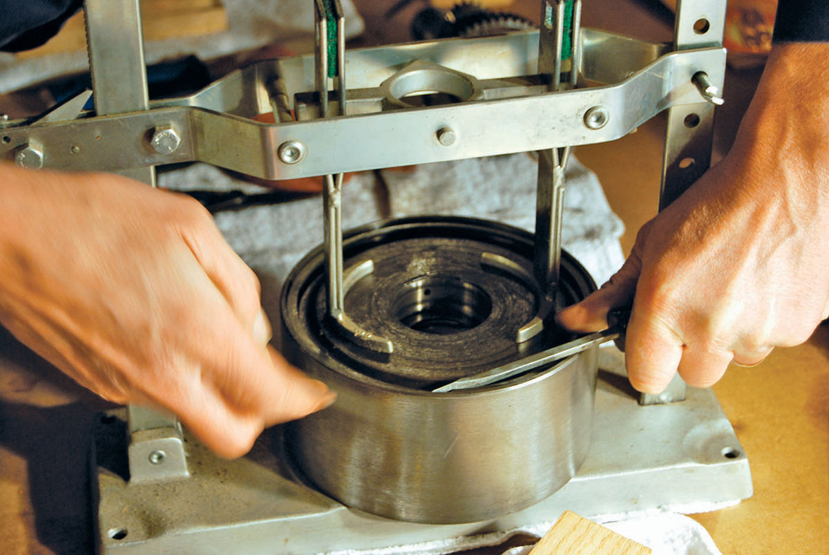
To service the front clutch you remove a snap ring from a recess in the front drum by holding the snap ring open with special pliers while avoiding the possibility of damaging the bearing surface. Take out the steel and bronze washers and rotate the carrier and drum with a twisting motion to line up the clutch plates. Use a bottle jack press and wood block to apply enough pressure to take out the snap ring securing the clutch drum in the drive pin hole. Then remove the annular piston from the clutch with a block of wood and soft pry tool.
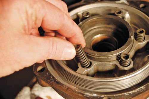
In our rebuild we removed the rubber seals and brass expanders from the annular piston by hand and replaced them with new parts (which would now include lip seals). We installed a new rubber seal and brass expander in the clutch drum. Then we installed new drive plates and driven plates. The Fatsco rebuild kits come with a large, poster-size illustration to help you identify parts and visualize how to install them properly. After the plates are installed, the next step is putting in the inner and outer clutch release springs. Then install the front clutch-driven center gear, tapping it onto the front drum with a soft hammer.
Servicing the Rear Planetary Assembly
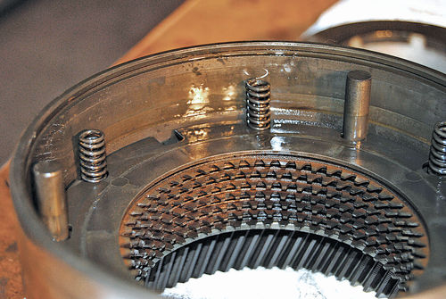
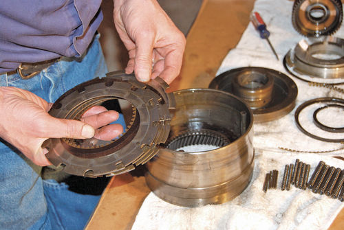
This assembly follows the design of the front planetary assembly, but goes at the rear of the transmission. Use snap ring pliers to remove the snap ring that holds on the rear clutch hub. Then rotate the hub out of the drum. With a drift in one hole, gently work the internal gear out of the rear drum. Use a magnet tool to extract the small coil springs from the holes. Then remove the old clutch plates.
Remove the next snap ring you come to and start the drum out using a rubber-faced mallet and a block of wood. With one hand on each side, lift the rear clutch drum out of the outer drum and pin assembly. There will be oil seals to replace (either seals and expanders or lip seals). After the new parts are installed, use a wood block to install the rear clutch drum, making sure it seats tightly against the snap ring that you replaced.
Put the clutch discs and springs in the rear drum, placing the outside guide pins in their proper positions. Install the bronze thrust washer in the rear clutch hub. Rotate the drum and hub until they fall into place, while making sure that all of the discs are engaged. Originally, a special tool was used to hold the hub in place so the new clutch discs would not slip off the hub. A Universal Transmission Clutch Drum Spring Compressor tool can be used instead and the parts can be secured together with long, inter-linked plastic electrical ties.
Servicing Front and Rear Bands
The front band mounts around the front planetary unit and is made to wrap around it twice. The rear band mounts around the rear planetary unit and wraps around only once. The bands are held in place and operated by the front and rear servo mechanisms as follows:
“N” — Both bands and clutches released.
1st — Both bands on, both clutches off, front & rear units in 100% reduction.
2nd — Front band off/front clutch on, rear band on/rear clutch off, front unit in direct drive and rear unit in 60% reduction.
3rd — Front band on/front clutch off, rear band off/rear clutch on, front unit in 40% reduction and rear unit in direct drive.
4th — Front band off/front clutch on, rear band off/rear clutch on, front and rear units in direct drive and 0% reduction.
Reverse — Front band on/front clutch off, rear band off/rear clutch off, cone clutch on.
Both bands should be inspected for burned appearance, wear, cracks or loose linings. Check the steel bands for distortion or cracks. Make sure rivets are tight. Check that the rear band strut aligns properly and pivots freely. The rear band release spring should have no distortion and be of the proper length. Inspect the anchor ends of the front band for broken welds or worn sockets. Do not pry or distort the bands because they are surface-ground for proper fit.
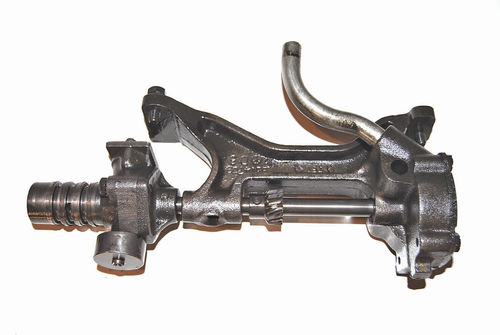
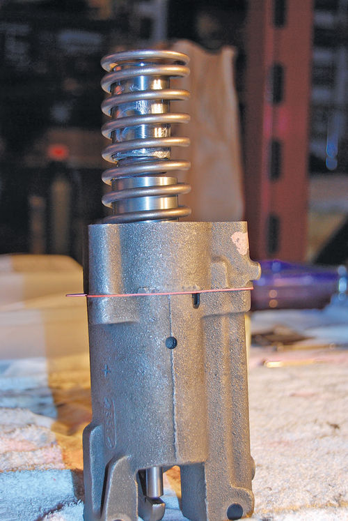
Servicing the Front Servo
These are mounted to the bottom of the Hydra-Matic housing where they can actuate the front band. They operate like a single-piston wheel cylinder in your brake system. The front servo is normally in the released position and is applied by means of oil pressure coming from the pump.
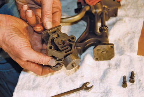
To service, remove the attaching screws holding the front band release cylinder to the body of the servo. Inside you’ll see a booster spring, retracting springs and servo piston. Take the front band release piston off the front servo piston by removing the two screws that secure the booster spring retainer and spring. Remove the front servo piston from the front servo body.
Remove the pipe plug and the spring type 4-to-3 valve retainer and take out the 4-to-3 valve. Next install the servo piston assembly being sure the dowel pin is in the proper position. Replace the retracting spring retainer.
Servicing the Rear Servo
The rear servo is mounted to the bottom of the Hydra-Matic housing and actuates the rear band through a lever that’s considered a part of the rear servo assembly. It is normally held in the on position by heavy springs and gets released by oil pressure. The springs that hold the servo in the on position are assisted by oil pressure when the car is moving with the rear band applied.
To service, use a bottle jack press to put the right pressure on the U-shaped bracket-type rear spring retainer, then undo the bolts securing it to the servo body. Remove the spring, compensator piston and outer spring. Then remove the inner spring and piston from the accumulator body at the top of the rear servo casting. Remove the booster piston.

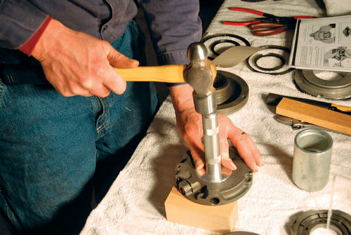
Next, remove the check valve plunger and rivet from the accumulator body. Replace any required parts, making certain that the plunger is placed in the notch in the accumulator body and that the check valve is positioned in line with the rivet hole. With a ball peen hammer and punch set the check valve rivet. Then use a plastic-tip mallet to put the applying spring into the accumulator body.
Servicing the Front Oil Pump
The front oil pump was part of the front servo casting from 1940-42. That style was driven by a gear on the transmission shaft. From 1946-52, the pump was an internal rotary gear-type mounted ahead of the front planetary unit. On the later cars the transmission must be disassembled to remove the front pump. Starting in 1952, a vane-type pump was used in the same position.
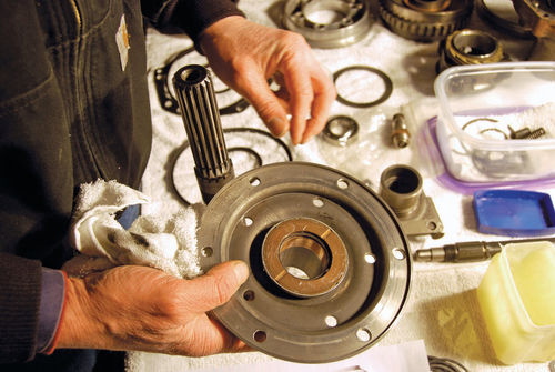
To service the pump, hold it stationary while removing the cover. Then remove the cover-attaching screw with a socket. With a hammer and chisel gently work the oil seal off the pump cover. Then install oil seal rings on the cover and use a proper size seal installer to push the oil seal evenly onto the cover. The pump body contains a drive gear, driven gear, relief valve spring and relief valve. Use a feeler gauge to hold the relief valve down when replacing the cover on the pump. To check the fit of the pressure regulator valve, make sure the coil fits freely over the valve and that the valve fits freely in the pump body.
Servicing the Rear Oil Pump
The rear oil pump is attached to the bottom of the Hydra-Matic case and driven by the output shaft. Start service operations by removing the governor drive flange. A special factory tool was designed to support the flange while a punch and hammer were used to remove it. A substitute support is easy to devise. When the pump is reassembled with new parts, the drive gear pin must be peened so it stays in the proper position.

Servicing the Governor
The governor is attached to the rear oil pump shaft and projects through the side of the opening in the housing. The governor’s oil delivery sleeve is connected to the valve body by tubes.
During servicing the plunger stop in the governor body can be removed after dealing with the oil delivery sleeve, oil seal rings, screws and plug. Install the plunger with a bushing and then re-install the governor valve plunger stop.
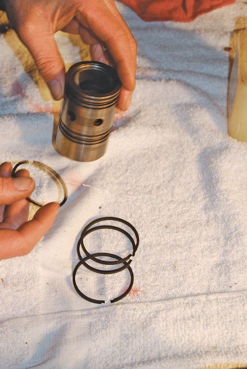
Servicing the Pressure Regulator Valve
The pressure regulator valve screws into the upper left front corner of the transmission case on 1946 and later cars. The valve was part of the front pump-servo casting before. The white metal part served as the regulator valve body.
This assembly consists of a 1 1 ⁄4-inch plug, a spring and the regulator valve. You should inspect all parts for nicks or scoring. Check to see if the springs are distorted or collapsed. Ours was broken but luckily, Fatsco had a good used one in stock. Also check all the drilled passages for foreign matter. The O-ring or gasket on the plug should be replaced. To assemble, put the valve and spring into the plug, coat with petroleum jelly to hold the parts together and place the assembly into the front pump before torquing the plug to 40 or 50 lb.-ft.
Servicing the Oil Delivery Sleeve
This is installed with the dowel toward the case. Tighten with the dowel in one of the two oil holes. Apply oil on each side of the bearing cap, and then apply air pressure to clutch holes in the side of the case. If you can see oil movement on the oil delivery sleeve, it is leaking. Install a new sleeve. If there is still a leak, the bearing cap will have to be smoothed with fine emery cloth until the leak stops.
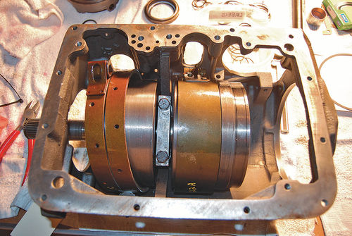
Servicing the Reverse Planetary Assembly
This assembly is mounted at the rear of the transmission case, behind the rear planetary unit. The reverse assembly is carried on the rear cover. Begin by driving the output shaft out of the housing. The factory supplied a tool that looked like an over-sized door crank remover to dislodge the ball bearing snap ring. Next, remove the speedometer drive gear by “bumping” the output shaft against a wood block. Then remove the reverse internal gear snap ring.
Separate the output shaft, which has steel and bronze washers at the bottom, from the reverse center gear and drive flange assembly. Remove the reverse drive flange snap ring. Saw, and then chisel a slot in the governor drive gear so it can be removed from the oil pump. The new bronze driven gear should be enlarged with heat so it will fit onto the pump. Reverse these steps to install the ball bearings and the speedometer drive gear.
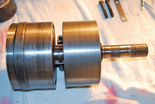
Checking Torus Members and Flywheel
The parts of the fluid coupling mounted at (not on) the flywheel make up the torus assembly. They are the driven torus member, the driving torus member and the torus cover. A number of springs, washers and snap rings complete the assembly. On the driven member the check valve bearing surface should be free of any scoring. Check the inside of the valve for scoring, as well. Check the movement of the valve over the hub and inspect and measure the 3 17⁄32-inch valve spring size. Check the torus cover oil seal hub for scoring. You may see a normal groove or two grooves (depending on model year) and you will have to determine if using a new ring will result in a less than .025-inch cover gap.
Inspect the gasket and hub splines for wear or damage and measure the run out. A dial indicator should show less than .005 inch of run out. If the torus cover run out is more than this and the flywheel run out turns out good, you can try to install the torus cover 180 degrees from its original position and re-check run out.
Inspect the flywheel, which rubs against the torus cover, for nicks or burrs and see if the flywheel teeth show any damage. Check the flywheel run out with a dial indicator making sure that it doesn’t exceed .005 inch.
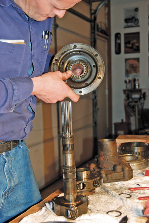
Inspecting the Main Shaft
The main shaft is the long, solid shaft connecting the driven torus member in front with the rear planetary assembly sun gear, which is usually an integral part of the main shaft. Inspect the shaft for damaged teeth and smooth thrust bearing surfaces. Fatsco may have replacement parts if the originals are badly damaged or worn.
Inspecting the Output Shaft
This is the solid, splined shaft that connects the rear planetary assembly pinion cage with a universal joint. This assembly incorporates the main shaft selection washer, the reverse unit planet carrier, the speedometer drive and the output shaft. All of these parts need to be carefully checked for damage, distortion or excessive wear.
This covers the basic servicing of 15 out of 16 basic units making up the fourspeed Hydra-Matic transmission. The 16th unit is the control valve assembly, which is a complicated device with many parts that we’ll talk about servicing in Part 3 of this series. Also in that segment, we’ll talk about reassembling the Hydra-Matic, making adjustments and road testing.


