
Tackling Several Engine Projects
After All of This Work, It’s Time for a Test Drive… Now Why Did That “Service Engine” Light Come On? And Where Is That Coolant Coming From?
Since we’re wrapping up John Armstrong’s engine project series with this installment, we thought we’d start with a letter we recently received from a reader regarding John’s approach. Here’s the letter:
I was wondering why he doesn’t just pull the engine out of the car. He’s done all the hard work already. He’s got the radiator out of the car, the exhaust disconnected; all the stuff off of the front of the engine. All he would need to do is take out the drive shaft and the transmission cross member. The engine and transmission would come right out. Put it on an engine stand and do all the repairs more easily, with better quality. Thanks, just wondering.
Jeffrey Moore GTI MILLWORK Wilmington, Delaware
Here’s John’s reply: Removing the engine is a valid option to consider. On this project however the thoughts of engine removal never entered the picture. I try and approach any project with the best method to do the job, and have it be an enjoyable project. In this case some things to weigh when making this decision would be:
Will removing the engine make any of the tasks easier?
Will the quality of the job be affected? Will it save time?
There was nothing encountered that would have been appreciably easier with the engine removed. Issues like the stuck casting plug and incorrect engine mount would still exist. Having the engine out and stand-mounted would allow you to be on your feet while fighting with the casting plug, so yes it would have been more comfortable, but there would still be the struggle to remove the old plug.
The engine mounts would no doubt be easier to remove, but unknowingly I was working with two left engine mounts and that problem would’ve still been an issue when trying to reposition the engine and line up the mounts. Even the cleaning and repainting was no hassle. There was some masking involved, but it wasn’t as though I was repainting the car. So while there were some bumps along the way, ultimately all the repairs went smoothly.
As to the question of job quality; if there had ever been a thought that performing the repairs with the engine remaining in the vehicle would compromise the quality, leaving the engine in place would never have been considered.
Time usually isn’t a big consideration for many of us working on our vehicles, but you want to make the best use of it. Removing the engine would require additional time. Start with removing the vehicle’s hood. And while there is a large amount of space with the upper fan shroud removed, definitely play it safe and remove the radiator and lower section of the shroud. Those dangling transmission cooling lines will need to come out; also disconnect the shift linkage, speedometer cable, solenoid wiring connected to the transmission, drive shaft, the transmission mount, and cross member. Plug the transmission rear seal to avoid leaking fluid on the way out. There will be a few small things like the O2 sensor wire, oil pressure switch wire, temperature sensor wire to the coolant gauge, a braided ground strap or two, and the TBI fuel lines that are secured to the front of the head. There is still additional work to be done once it’s out. The torque converter will need to be unbolted from the flex plate, and the transmission unbolted from the engine and set aside. Now the engine is ready to be hoisted again and mounted to the stand.
Keep in mind you will require the space of an additional bay to work on the stand-mounted engine, as well as store all these removed items.
Certainly there are times when you make a change in plans due to a newfound problem. That’s happened to all of us at some point. Ultimately if you feel more comfortable removing the engine, go for it, but it wouldn’t be a time saver. Now, back to our series:
Time for the Engine Timing
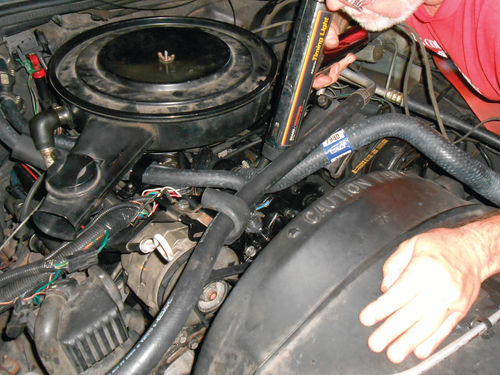
With the engine up to operating temperature, at proper idle speed and the transmission in drive, the timing is checked. As you can see in Photo 185, the path of the strobe has to find its way between the timing chain cover and the back of the water pump. Hoses are encroaching to block the beam as well. On top of that, there must be enough room to be able to actually see the timing mark. The mark is positioned almost straight up, so there is a tendency to want to hop up into the engine compartment, except there isn’t enough space. So it’s a good stretch over the fender while keeping the timing light cords and body parts clear of the fan. While you can’t see it in the photo, the wire from the timing light to the #1 ignition wire was secured to the A/C high pressure hose with Velcro to avoid the fan, while the connection to the battery runs up in front of the fan shroud. To make them easier to see, both the notch on the harmonic balancer and 0° mark on the timing plate were marked with white paint. Something else worth mentioning is that the timing plate also has a special hole to accommodate a magnetic probe timing device. This would eliminate the need to actually view the timing mark, and make the job easier. This type of equipment is usually pretty costly, reserving it primarily for the professional shop.

As suspected, the timing was within a few degrees and after making the adjustment I was anxious to take a drive…it seemed like the vehicle had been apart forever.
The first run was a 35-mile road trip, and along the way the service engine light came on, and the throttle response became very lethargic. Once back home it was determined to be a code #43, a fault in the Electronic Spark Control (ESC) system. Obviously this required attention. Knowing a little about how the system works makes diagnosis a bit easier and more understandable. Here is Chevrolet’s description: “Electronic spark control is accomplished with a module that sends a voltage signal to the ECM. As the knock sensor detects engine knock, the voltage from the ESC module to the ECM drops, and this signals the ECM to retard timing. The ECM will retard timing when knock is detected and rpm is above 900 rpm.”
Looking at the first prompt on the diagnostic chart in the Chevrolet manual I quickly realized my scan tool wasn’t sophisticated enough to perform some of the described checks. It reads, “SCAN set on knock signal. Is there a knock signal indicated?” This scan tool has no such setting. The preceding page in the manual gives a verbal description of each step in the diagnostic chart, explaining what’s being done. This was helpful, and added to the information in the Haynes manual, some checks could be performed using a basic test light and timing light.
The Haynes manual suggests the following tests: With the engine running at 1500 rpm tap on the engine with a hammer near the knock sensor while watching the ignition timing; it should retard. If you have a good-quality digital tachometer connected and the rpm is steady, you might be able to notice the rpm drop as the timing retards. That’s easy enough to do alone, but a second person to do the knocking is a much better choice when trying to observe the timing mark at the same time. If you have access to an “advance” timing light (the style with a knob on the rear for checking advance curves), it will allow you to reposition the timing mark, making it easier to see and reference. If the timing doesn’t retard, shut off the engine and disconnect the wire to the knock sensor. That was the situation with the El Camino. Next connect the clip of your basic bulb-type test light (do not use a Power Probe tester) to battery positive, and temporarily relocate the knock sensor wire where it will be easiest to reach and touch with the test light. As previously stated, have the engine running at 1500 rpm and touch the test light probe to the wire connector for the knock sensor while observing the timing mark. It should retard each time the connector is touched, and it did on the El Camino. The rpm on the tachometer also decreased ever so slightly each time. So the knock sensor was defective. Had the ignition timing not retarded, the ESC module may be defective. But before running out and replacing it they suggest checking the wiring at the ESC connector.
1. Check for battery voltage with the key on at the pink/black wire terminal (B).
2. Check for ground continuity at the brown wire terminal (D).
3. Check for continuity to the knock sensor at the dark blue or white wire terminal (E).
4. Check for continuity to the ECM at the black or yellow wire terminal (C).
The first three checks are easy enough to perform, while checking the wire to the ECM will take a bit more effort.
The knock sensor was replaced, and performance was back to normal. To clear the code from the computer, the battery was disconnected for 30 seconds and then reconnected. Knock sensors are sensitive, so you don’t want to drop it or bounce it around. Failure when reinstalling a used knock sensor is not uncommon, at least in my experience.
Looking for Oil Leaks
The next day I returned to my favorite position lying on my back under the vehicle. While visually inspecting for any signs of leaks, at first glance all looked OK. All the casting plugs and the knock sensor were dry, so that was good news, and no oil on the block, or from around the pan gasket.
To go a step further, dye will be added to the engine’s oil to further check for any leaks that might be small or hard to spot. Photo 186 shows the Tracerline Dye-Lite additive that will be used. It can be added to gasoline or diesel engine oil, gasoline or diesel fuels, automatic transmission and power steering fluids, as well as standard hydraulic and lubrication fluids. There is a different additive used for cooling systems. They recommend adding ½ oz. per 4-6 quarts of engine oil in gasoline-powered vehicles. If the oil is extremely dirty, either change the oil first or add extra dye. The dye can remain in the system until the next change interval without diminishing the oil quality. The dye is added as if it were oil, and then the engine should run for 10 minutes, allowing time for it to completely mix. Shut off the engine and let it cool until it is comfortable to work around. It’s best to work in a slightly darkened environment. For example, during the daytime, inside a garage with the lights off is perfect. There’s plenty of light to see, so it’s not like you will be bumping into things.
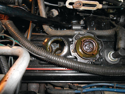
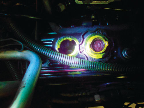
They suggest doing a quick test before chasing after leaks. Use the UV light and inspect the dipstick or oil fill port for a bright fluorescent glow. Take a look at this comparison. Photo 187 is a view with the oil fill cap off, the way it appears to the naked eye. Next in Photo 188 you see it with the aid of the UV light. It appears like someone poured mustard inside the valve cover, and managed to drip some on the outside too. Search for leaks in all the obvious areas like gaskets, seals, oil pressure switches, the distributor base and so on. This engine is clean, and any leaks should be easy to spot. Even if the engine were covered with oil from years of neglect, the dye will show off the fresh oil leak just like it did in Photo 188.
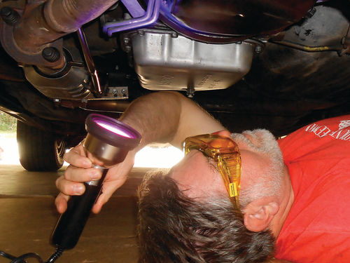
In Photo 189 the UV light is being used to look for evidence of leakage around the rear main seal area. This light has a bright 100-watt bulb, and is powered by the vehicle’s battery. And those yellow glasses I’m sporting weren’t something purchased from a TV infomercial; they came with the Tracerline kit. They protect your eyes from UV rays and enhance your ability to spot leaks. No oil leaks were spotted. I don’t know how long the dye will remain effective in the system, or how quickly the engine heat may break it down, but the El Camino will be driven for a while and then rechecked. As was done initially a check inside the valve cover fill port, or of the dipstick will tell if it’s still showing up bright yellow, and if so any leaks would show up the same way.
A Stubborn Coolant Tank Leak
In the meantime the level in the cooling system overflow tank had dropped, and the area where the hose connects to the tank was wet. The clamp was found to be broken in half, so that had to be it. But naturally even with a new clamp it continued to leak.
The tank was removed, cleaned and inspected. This entailed blowing into the fill hole and plugging the outlet port with one finger while my wife sprayed soapy water around the suspected area. Let me repeat, the tank was completely cleaned prior to testing. All appeared to be OK, so the hose must have been the problem. The hose looked OK, but certainly it’s the original one that came on the vehicle. The best choice would be to simply replace it, but for the moment it will be reused. About 1½” was removed from the end that had been connected to the tank.
The hose was reconnected…and it still continued to leak. Once again the tank was removed. A snug-fitting vinyl plug was placed over the outlet, and the tank filled about half-full with water. Sitting inside the house on a piece of newspaper it could be checked regularly. Any wet spots would easily be seen on the newspaper, and traced to the origin. The plastic welder kit was out and prepared for service if needed. Certainly it must be a seam that has a very slow leak.
Almost immediately there was a spot on the paper by the outlet port. The plug wasn’t as snug a fit as believed, so a clamp was added, and from there on it remained dry. A phone call was made to NAPA and they have the hose in stock, so on the next trip into town a new hose will be purchased. Thankfully other than that, there is no sweet antifreeze smell, and the engine is dry. Nonetheless, the cooling system will be pressure tested to double check for leaks. It’s difficult to see much of anything behind the flex plate on the rear of the engine, but while under pressure the video scope will be used again to get another look at those casting plugs. If nothing is seen on the camera, and the cooling system maintains its level, then there are no leaks, and the only leak was that around the knock sensor. If the wet area around those rear casting plugs doesn’t show up yellow under the UV light, then it is residual oil from earlier leaks, and this job is complete.


