
Tackling Several Engine Projects Pt. 3
This Time We’re Going to Remove Valve Assemblies, Check Some Components and Clearances, Install New Seals…and Do Some Reassembling.
Editor’s note: When the author decided that the 4.3-liter V-6 engine in his 1987 El Camino needed some attention, he pulled together a list of repairs to perform. When we last visited with him, he was turning his attention to valves and valve stem seals. There have been 28 images in the series so far, so we’ll start here with Photo 29.
Replacing the Valve Stem Seals
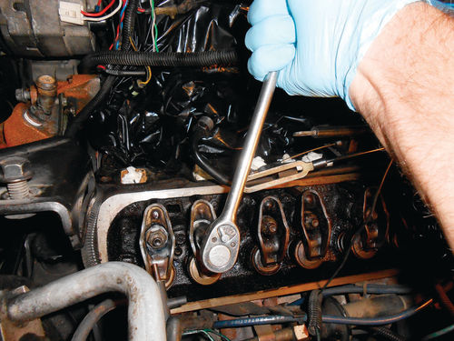
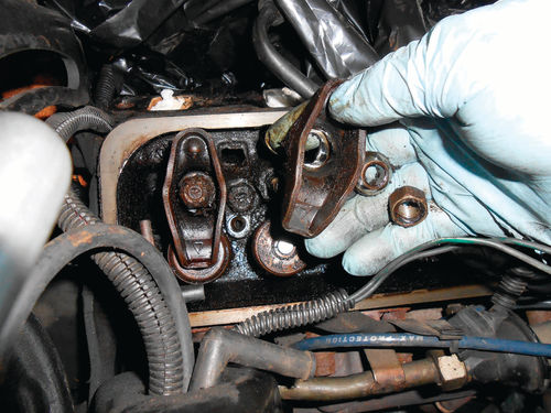
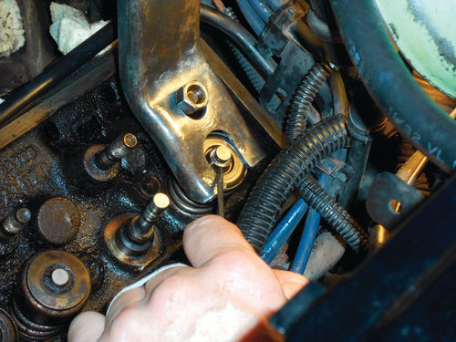
Back to the present… In Photo 29 a 3 ⁄8” drive ratchet with 5 ⁄8” deep socket are used to loosen and remove rocker arms. Once removed there will be three pieces. The rocker arm, nut and pivot ball, all seen in Photo 30. This work can be performed either before or after the cylinder is pressurized, it makes no difference.
Note that these images show work being performed on the #1 cylinder. However, a bit later some tasks are shown on other cylinders as well.

Make sure to keep all intake parts together, and do the same with the exhaust; don’t mix them. Photo 31 shows a valve organizer that was made years ago. It includes spaces for the valves, springs and pushrods too, in the event you’re taking the heads entirely apart and doing a valve job. This is simple to make and the cost is minimal. Big zip lock bags or tin cans will also do the job, just remember to identify intake and exhaust parts, and the cylinder they came from if you decide to take apart more than one at a time.
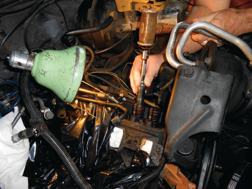
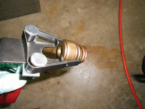
Next is to free the valve keepers from the valve cap. Their tapered fit makes them stick together. For this use either a small section of pipe or a deep socket. Center it over the top of the valve cap and give it a tap with a soft-faced hammer as seen in Photo 32. Sockets allow you to use an extension if needed, and the copper hammer won’t damage any tools.
If you can feel the valve spring yield slightly, and no release of air pressure from the cylinder, then the keepers are free and that valve spring is ready to be compressed and removed. On the other hand, if the valve spring feels solid, and you hear a large release of compressed air, repeat the procedure. Usually a couple of taps will free the valve keepers.
There are a couple of different methods to compress the valve spring with the cylinder head remaining on the vehicle. Photos 33a&b show using KD #912 valve compressing tool made to fit Chevrolet. It mounts in place of the rocker arm on the stud. This tool is readily available for less than $15. Kent Moore #J-5892-D is another option. Though a similar-style tool, it mounts in the opposite direction. In other words, your arm doesn’t extend over the valve, it’s a shorter reach. It would seem the Kent Moore tool would be easier to control, but the price is harder to swallow. It starts around $70 on eBay and several suppliers show it in the $120 range.

Once the tool is secured to the stud, pull it toward you, compressing the valve spring. Compress the spring enough so that the keepers are sufficiently exposed and while holding it there, use a small magnetic pickup tool to grab both keepers as seen in Photo 34. Photo 35 shows them removed. I would advise against using a telescoping magnet unless its length can be locked. The last thing you want while one hand is occupied compressing the spring is for your 6” pickup to become 18” long because its strong magnet wouldn’t let go of the valve cap. This small Craftsman pen-style magnet is perfect. In some instances you may need to disturb the keepers with a small screwdriver or pick tool to get them loose. With the keepers removed, pressure can be released from the tool, and the spring is now loose and free to remove.
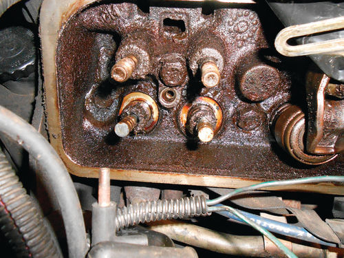
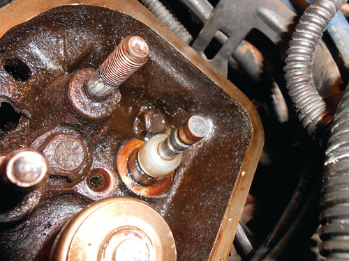
If you find the spring is stuck, the round valve stem seal has become so hardened that it doesn’t want to let go. In this event, use the same socket and hammer and tap on the valve cap a few times to release it. It won’t take much. Lift off the valve spring and its components, and if there are any shims underneath, make sure they are kept with that spring. Photo 36 is the view with both the valve springs removed. In Photo 37 I have removed the intake valve umbrella seal. If you compare the photos you might be able to see that it was removed from down at the base, over the valve guide. It may take some prying and twisting, but eventually it simply pulls off.

Next is to check the valve guides for wear. Shut off the air supply to the cylinder and once the pressure is low enough, the valves will drop free. The piston is all the way to the top of the cylinder, and the valves drop only about 3 ⁄8”. To check the valve stem clearance you will need a dial indicator. The manual suggests clamping it to the rocker arm cover gasket rail, but a much more reliable mounting point was a 3 ⁄8” intake bolt threaded back into the head. The valve should be held so that it is 1 ⁄16” off of its seat, and the reading should be taken as close as possible to the valve guide. Move the valve back and forth in the direction of the indicator as shown in Photo 38. The clearance should not exceed .004” for the intake, and .005” for the exhaust. Due to the diameter of the dial indicator, it wasn’t possible to position it as close to the valve guide as hoped for. The further away from the valve guide the reading is taken, the greater it will be. The reading was rechecked with a smaller indicator and found to be within specifications. Unfortunately, due to the position in which it was mounted, the indicator completely blocked the view of the valve stem, so photogenic, it wasn’t.
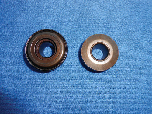
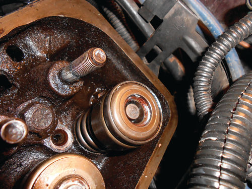

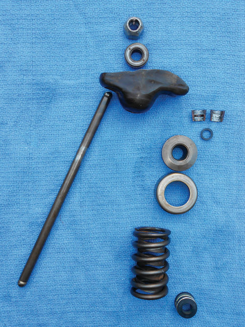
Now is a good time to clean and inspect the removed parts. In many instances simply cleaning the parts in a parts washer or with cleaning solvent on a rag would be enough. These heavily grunge-laden parts will first be taken over to the wire wheel, and then to the parts washer. Look for excessive wear to the contact points of the rocker arm, as well as tiny cracks. Make sure the pushrod’s oil hole (if your vehicle has hydraulic lifters) is clear and they are all straight and true. Rolling each pushrod on a small flat pane of glass is a fairly reliable test. Look over the pivot ball for any pitting or noticeable wear. A visual inspection of the valve spring is all I do, but the service manual will advise you about checking spring tension as well as installed height. Photo 39 shows the parts that have been removed and cleaned for one intake valve. Starting from the top is the rocker arm adjusting nut, pivot ball, and rocker arm. Over to the left is the pushrod, and on the opposite side are the valve locks (keepers), O-ring stem seal, the valve cap (on the exhaust valve it’s referred to as the valve rotator assembly), the oil shedder (or shield), valve spring, and the umbrella seal. Photo 40 shows the intake valve cap at the bottom, and the exhaust rotator cap at the top. The rotator cap actually has bearings in it, and as the name implies is designed to allow the valve to rotate. It is easy to spot. Clean and inspect to make sure they all rotate freely. Dry the rotator with compressed air if it has been submerged in cleaning solvent, and oil it before installing.
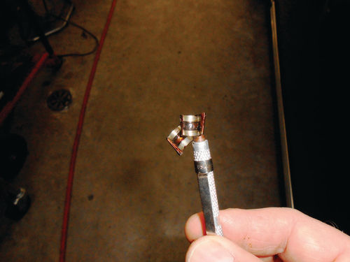
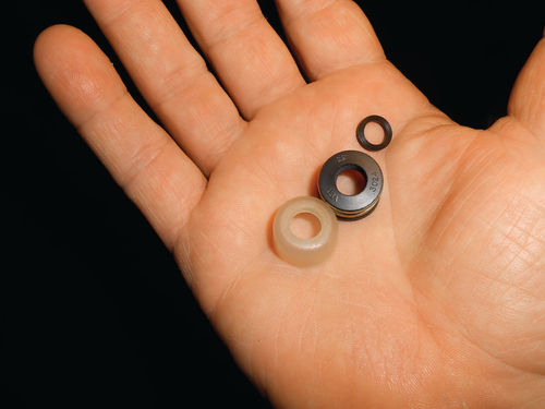
On the El Camino there is still cleanup work to be done, getting as much sludge as possible out of the cylinder heads. With the valve springs and all off and out of the way, this cleaning process is easier. Photo 41 shows the valve seals that will be used. The translucent one on the left is the umbrella seal for the exhaust valves. It’s hard, possibly made of nylon or some more exotic material. The black one appears to be made of rubber and will go on the intake valves, and the small O-ring to the right will be used on each valve stem.
Time to Start Putting It Back Together
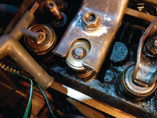
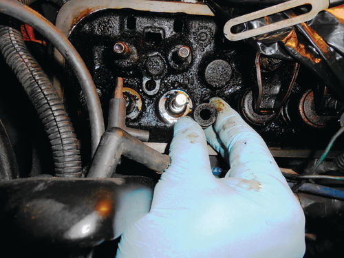
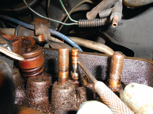
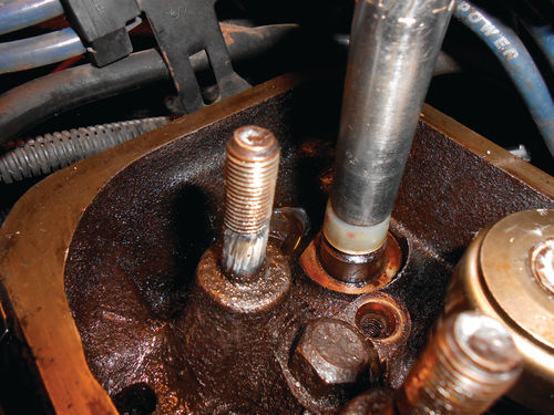
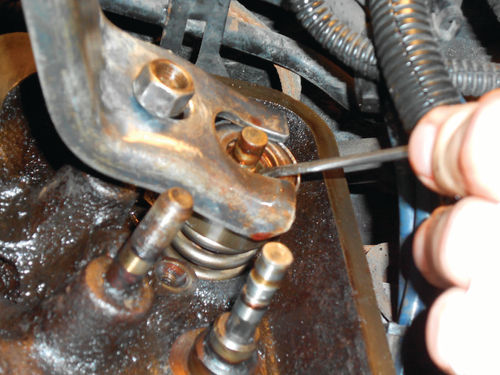
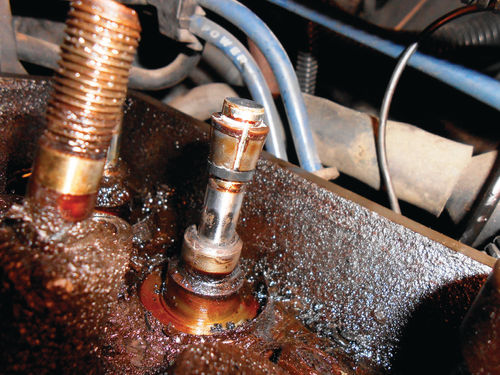
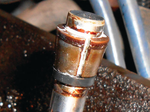
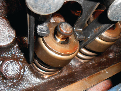
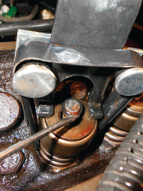
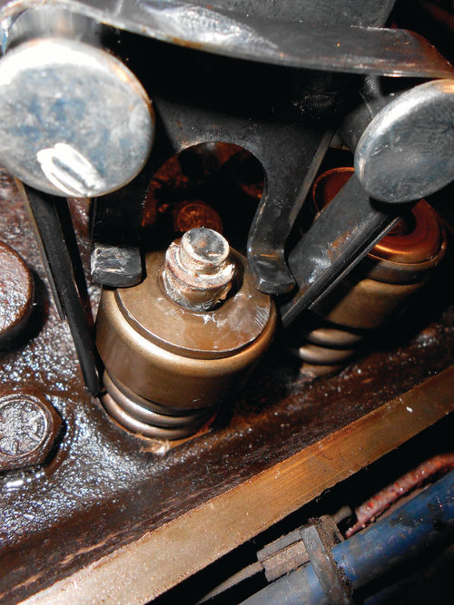
Slowly turn the compressed air back on until you can just hear it leaking past the valves. Then go over to the engine and grabbing both valve stems, raise both valves back up against their seats. The air pressure will immediately hold them in place. There are two grooves in the top of each valve stem. The top one is where the valve keepers lock in, and just below is the groove for the O-ring seal which is being indicated in Photo 42. Make sure these grooves are clean, and wiping off the end of the valve stem with a small amount of solvent on a rag won’t hurt. Coat both the valve stem and the new umbrella seal with some oil. Photo 43 shows the exhaust umbrella seal installed. Pushing it straight down over the stem is often easier with the aid of a deep socket as seen in Photo 44. This will help keep it straight and make sure it’s completely seated. Using the same KD tool #912 for installation, it’s time to replace the valve spring and shims (if there were any), along with the oil shedder and then the valve cap, as shown in Photo 45. Next mount the tool on the stud again but the pivot ball will remain out. With the expanded valve spring in place, the stud isn’t long enough to accommodate both the ball and nut, only the nut. This makes this tool prone to walking back and forth on the valve cap. A flat washer can be used in its place, but it doesn’t make a huge improvement. The O-ring seal should be lubricated with oil and ready to go. As you might imagine, you must have everything within easy reach of your one free hand once you get started. Now compress and maintain pressure on the spring with one hand, and start the O-ring onto the valve stem using available fingers of the other as seen in Photo 46. The first groove it drops into is for the keepers, so don’t stop there. As an aid, use a small pocket screwdriver and gently work around the perimeter of the O-ring and push it down farther into the valve cap as is being done in Photo 47. As the O-ring gets deeper into the taper of the valve cap, the fit becomes snugger. Sometime you will feel the O-ring drop into its groove, but usually it’s hard to detect. In Photo 48 the screwdriver tip is pointing to the installed valve keepers. If they can easily be fit into place, the O-ring is likely in its groove. Often you feel slight resistance before the first keeper locks into place. This is because the keeper pushed the O-ring fully into its groove. In Photos 49a&b the valve spring has been left off to show the position of the O-ring with relation to the keepers. The keepers sit directly over the stem seal O-ring. Using some grease on the inside of each keeper is a good way to retain them to the valve stem. Once both keepers are in place, slowly release the pressure from the spring while watching the valve cap to make certain all remains in place. These O-ring seals are easily dropped and lost, and if you happen to get into a struggle with the valve spring, they may be damaged. Fortunately, they are inexpensive. For that reason I would highly recommend purchasing a second box of them to have on hand. If you even suspect an O-ring has become damaged during installation, remove the spring and replace the O-ring.
If Performing These Tasks Is Difficult With One Hand, Try This…
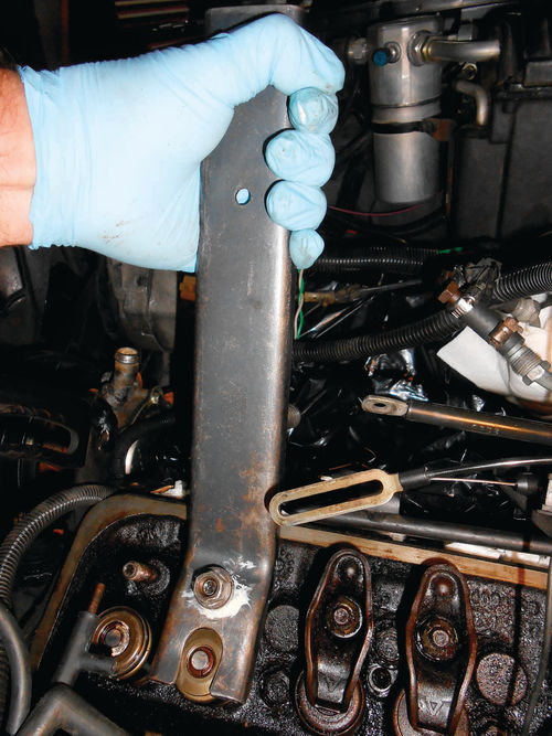
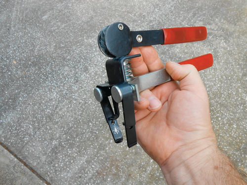
I have found using the KD tool for disassembly is fast, and works great, but prefer to use a small valve spring compressor tool for installation. Naturally it can be used for disassembly as well. Photo 50 shows the Lisle #16570 ($25 at Rock Auto). It allows you to load the spring into it and compress it before having it placed back on the head. The two arms hook in near the base of the spring, and then while holding the lower handle the top one cams down to meet it, compressing the spring, and locking it in the process as shown in Photo 51. This gives you the freedom to walk away should the need arise, and allows you to have both hands free for retrieving dropped keepers and more likely avoid dropping them in the first place.
With the umbrella seal in place, the tool with the compressed spring can be placed down over the valve stem and the stem seal started as seen in Photo 52. If for any reason it doesn’t appear the spring is compressed enough, slowly release the top cam handle until the pressure is completely removed from the spring. Then rotate the handle clockwise as many turns as is needed until the spring compression is sufficient to easily install the O-ring and keepers. Just as before the O-ring is pushed down using a small pocket screwdriver as shown in Photo 53.
Photo 54 shows the keepers in place with the aid of white lithium grease. Slowly release the top cam handle while watching to make sure both keepers remain in place. Should you find yourself working in a tight area that won’t allow the vertical operation of the tool’s cam handle don’t worry, the tool includes a 2”-long, 1 ⁄2”-diameter bolt that can be inserted in its place. The spring is now compressed with the horizontal movement of a ratchet or wrench, maybe not as convenient as the handle, but it won’t be necessary that often.
Next, we’ll adjust some valves and clean some parts.


