
Tackling Several Engine Projects Pt. 6
Time to Work Down Under
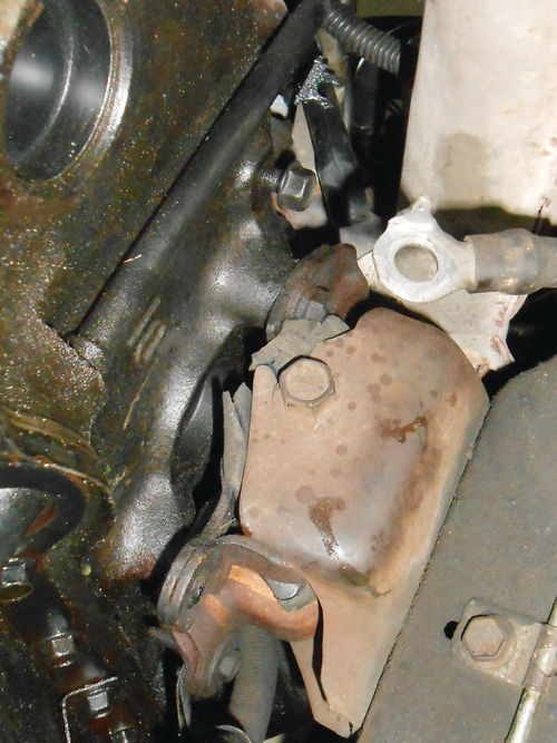
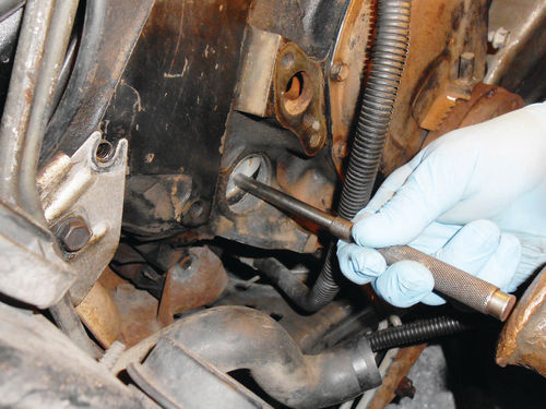
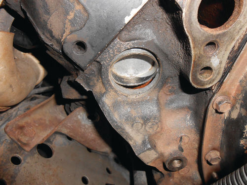
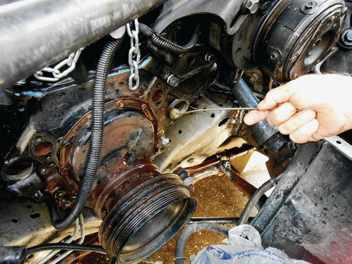
To drain the remaining coolant from the engine, the knock sensor is threaded out of the left side of the block. That’s it in Photo 90 just above the oil pan. Squeezing the wire connector will release it from the sensor. Now use a 7/8” deep socket and ratchet to thread it out as seen in Photo 91. These sensors are usually very tight, so don’t be surprised. That’s why my normally idle 1⁄2” drive ratchet was put to use. This one came out without a fight, though, and wasn’t too tight at all. Once the sensor was removed, there was enough of a sediment buildup in the block that not a drop of coolant came out. The tip of a screwdriver was used to poke through the sediment barrier, and that solved that problem.
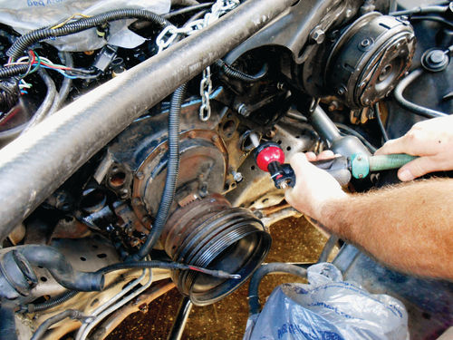
There is still a drain plug on the opposite side of the block, but the starter will need to be removed first to gain access. A 10mm socket and extension quickly removed the four retaining bolts of the torque converter cover shown in Photo 92. It’s made of plastic, so as long as it’s not damaged, all it requires is cleaning.
Next disconnect the starter solenoid wiring. A 15mm wrench was needed to remove the positive battery cable from the solenoid, and an 8mm socket for the small wire from the switch terminal. Note, the battery has been disconnected since the beginning of this project, otherwise that would be the first item on the list before even touching the positive cable at the solenoid.


With both wires free, disconnect the starter’s tail support bracket. There’s a stud extending from the rear of the starter with a 7/16” nut that secures it to the bracket. A ratcheting box wrench was used to remove it, while a 1⁄2” swivel socket on an extension was a good choice for loosening the other end bolted to the block. The starter is secured with two 3/8” bolts that require a 9/16” socket and extension for removal. Remember these starters tip the scale at about 20 pounds, so be prepared when the last bolt is threaded out. Pay attention for any shim spacers placed in between the starter and block. If there is one, make certain to replace it when the time comes.
The starter exited between the exhaust crossover pipe and the lower control arm. Naturally, it was a bit of a dance to get it out. The easiest method was to rotate it so that the solenoid was facing the floor; essentially removed turned upside down.
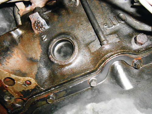
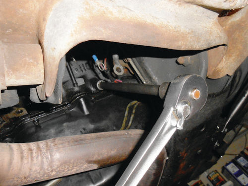
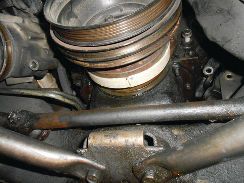
Photo 93 shows the casting plug and drain plug that were hidden behind the starter. The same 1⁄2” drive ratchet was used to remove the drain plug, but this time with a 10” extension and 9/16” socket as seen in Photo 94. This area between the exhaust pipe and lower control arm is also where the starter found its way out. The exhaust crossover pipe is coming out so the oil pan can be removed. Had I removed it first, the starter removal would naturally have been a bit easier. I guess the starter has been out so many times over the years that taking the crossover pipe down first would have felt like cheating.
Soaking Those Rusty Studs
The El Camino has no northern history to my knowledge; however the exhaust manifold studs are still extremely rusty. WD-40 was liberally applied to all of the manifold studs and allowed to soak as you can see in Photo 95. If the nuts don’t release with minimal effort, an oxyacetylene torch will be used to heat and expand the nuts. As rusty as these studs are, they may be replaced before all is put back together, but I certainly don’t want to break them trying to remove the nuts. While the penetrating oil was working on the studs, the flange was disconnected between the crossover pipe and catalytic converter. This went smoothly, certainly because the converter had been replaced not too long ago. Finally, a 9/16” deep socket on a long extension with a long-handle 3/8” drive ratchet succeeded in removing all the nuts without breaking any studs, and the crossover pipe was removed.
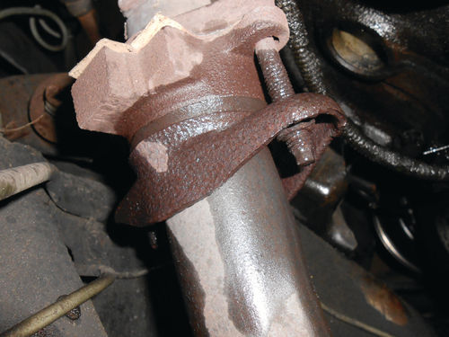
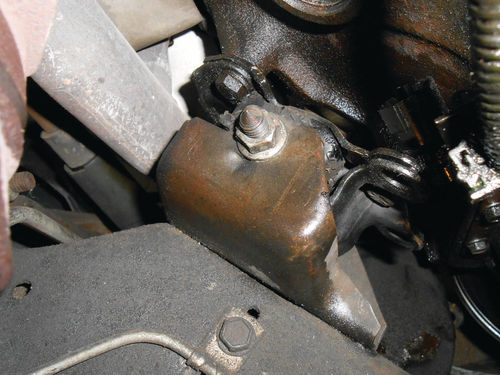
Photo 96 shows the left-side engine mount. Judging only by its appearance, it looks OK. That, however, is definitely not the case. Looking at the right-side mount in Photo 97, you can see the rubber hanging out; certainly a sign there is a problem. These both need to be removed to access the casting plugs located behind them and new mounts will go back in their place. A 5/8” socket will fit the head of the through bolt, while the nut on the other side is 11/16. Once the nut had been removed on the left engine mount through bolt, it could easily be pulled out by hand. While true with the left mount, that wasn’t the case with the other. An air ratchet is handy in this situation. Using a 5/8” socket on the head of the bolt, the ratchet was able to turn the bolt and gradually back it out of the mount. One could argue that you are going to take the load off the bolt when the engine is lifted, so just wait and pull it out then. That’s true, but if you are working alone you can find yourself going back and forth, something like this: the bolt is still binding; did you raise the engine too much? Or maybe it’s not lifted enough?
Anyway, with the bolts out the engine is poised and ready to lift. Just remember to remove the distributor cap or you will be making a trip to the auto parts store for a new one.

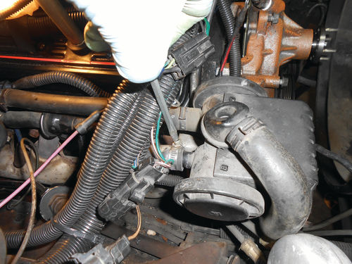
Although it will be awhile before the oil pan is removed, you want to make sure the crankshaft counterweights are rotated so they are positioned up in the block. Positioning the harmonic balancer timing mark at 6:00 as shown in Photo 98 will do just that. With the crossover pipe removed in Photo 99, the oil pan looks much more accessible. Note: There is a steel AIR tube that extends from the AIR (air injection reactor) pump’s diverter valve to the catalytic converter. Initially the small pipe was going to be disconnected from the converter to avoid accidentally breaking it due to the sagging exhaust and lifting of the engine. (You learn from your mistakes, and that exact situation happened to me on our Caprice.) When removing the crossover pipe I realized the converter was firmly supported by a bracket connecting to the transmission mount, so the exhaust was secure. As long as the bracket holding the small pipe to the rear exhaust manifold bolt was disconnected, it could safely remain connected to the converter without fear of damage. Just to be extra safe, Photo 100 shows removing the hose clamp and then the hose at the other end of the plumbing. While the plastic conduits of wiring block a good part of your view, look at the lower left corner of the photo and you can see the round check valve in the AIR tube that then disappears into the abyss. It’s now 100% free of the engine. This is also much easier than removing the connection at the catalytic converter.
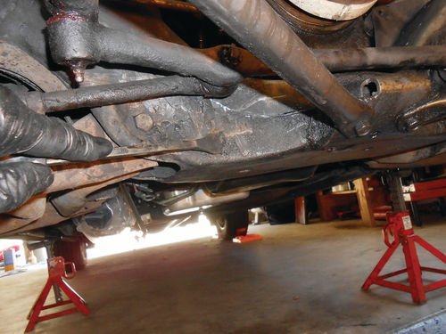
Photo 101 shows the layer of thick heavy grease was scraped while the vehicle was still in the garage. A large pan was underneath to catch the mess, but the washing would take place in the driveway.
Brains Over Brawn Equals Less Back Strain
In the past I had always (like most, I imagine) pushed vehicles in and out of the garage by hand when they couldn’t be started. But reading items in AR with regard to doing things differently as we advance in age made me think about this practice. Why take a chance on hurting my back grunting the vehicle back and forth. Thoughts of using our small garden tractor, and somehow utilizing a chain with a length of pipe over it to connect with the El Camino came to mind. The idea of sitting and letting the tractor do the work was brilliant! The next morning things got better yet as I remembered that there was a tow bar for a car rotisserie I have that might work perfectly.
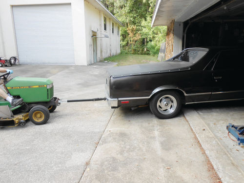
In Photo 102 there is a ball mounted to the front the tractor, and the tow bar has a 2” square pipe that fits into the hitch receiver of the vehicle. The construction is from two sections of 2” square pipe, a short and a long piece. The short section is drilled so that it can be pinned into the hitch like any hitch head, and the long piece has a ball coupler welded on it, in this case for a 1 7/8” ball. The two sections of square pipe are joined so that there is a vertical pivot joint. Now moving the vehicle is a very easy and safe one- person operation.
Washing & Drying the Engine and Frame
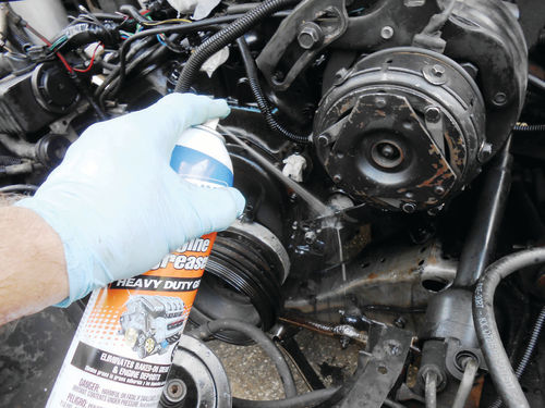
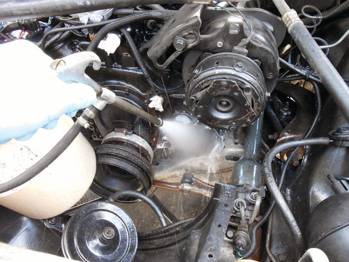
Once out of the garage, the front of the vehicle was raised enough to allow comfortable access to get underneath and wash and rinse everything. It was then safely supported and the rear wheels chocked. The engine and surrounding frame were sprayed liberally with Gunk engine cleaner as is being done in Photo 103. It was allowed to soak for a while, and then reapplied. Next a mixture of Dawn dish soap and hot water was mixed in a bucket for stage two of the cleaning. To apply the solution, a siphon gun was connected to my air supply and its pickup tube submerged in the bucket of Dawn and hot water. A pull of the trigger gives a strong blast of soapy water as seen in Photo 104. This too was allowed to soak for a bit, and then everything was rinsed with the garden hose. In addition to my daily eyewear, a full face shield was worn. This was mainly to help avoid spray-back from the Dawn and water solution. No doubt you’re going to get wet; it becomes a question of how much. A pressure washer is certainly another option for cleaning if needed, but remember the high pressure can also find its way into the wrong places.
A little time was allowed for things to drip dry, and then a couple of fans were set up to help things along. Once all appeared to be dry, the vehicle was lowered back to the ground, and pushed back into the garage the same way it came out.
Removing the Casting Plugs
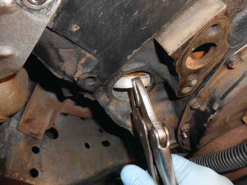
The casting plugs are going to be removed from the block, and while they’re out the garden hose will be used to flush as much internal build-up as possible. Once the block is thoroughly rinsed, new casting plugs will be installed. With the El Camino sitting level on the ground, those front two casting plugs couldn’t be any easier to access. A drift pin and hammer are used to knock the plug in as seen in Photo 105. You want to drive only a portion of the casting plug inward while allowing the opposite edge to be pried out with the aid of a small screwdriver. It should end up positioned something like Photo 106. Next a pair of Vise-Grips is used to get a bite on the exposed edge of the plug as seen in Photo 107. The Vise-Grips are then leveraged against the block and the plug pulls out. Naturally things don’t always work out exactly as planned, so don’t be alarmed when the entire casting plug goes inside the water jacket of the block. A good magnet tool is usually all that’s needed to retrieve the plug and bring it back up where it can be grabbed with Vise-Grips. These two front plugs have enough room inside the water jacket to easily cam them out during removal. Certain side casting holes may be fairly close to the cylinder walls, so depending on the location, if a plug drops completely inside you could face a bit of a challenge. This happened to me with the casting plug located behind the starter. The plug didn’t tip as desired when it was driven inward and it went completely inside the water jacket. This wasn’t too surprising, after all in this case you’re working on your back on the floor, and even though the vehicle is elevated, the task has been complicated considerably. The same thing had happened with the plug on the opposite side of the engine, but it was easily retrieved with a magnet, and removed with Vise-Grips. So what happened this time? While the plugs are on opposite sides of the block, the locations are not exactly opposite, so the clearance inside the water jacket isn’t the same. On the left side the casting hole appeared to line up in between two cylinders, and there was plenty of room to move the plug around. That was not the case with the plug located behind the starter. Due to the angle at which I was working, the plug pushed inward and also went up between the cylinder wall and block. It seemed like as good a position as any to grab onto the plug and start pulling it out. That was my first mistake. To better visualize what happened, take a look again at Photo 107. Here the casting plug is being grabbed from its uppermost edge, in a sense drawing it up and out from the bottom of the block. The plug behind the starter was exactly the opposite, trying to pull it down and out. When attempting to repeat the process that had worked so well on the other three casting plugs, this one wasn’t willing to exit. With the plug being positioned where it was there simply wasn’t enough room to cam and rotate it out smoothly like the others.
Instead of pausing and thinking about what was going on, I simply pulled harder, even repositioning the Vise-Grips attempting to get a better approach. That as the others. Back to the problem at hand; thoughts of using a Dremel tool and small cutoff wheel, or even drilling several holes in the plug to weaken it so it could be collapsed on itself and be removed were considered. These both seemed like ideas with merit, but now I was being cautious, wanting to make sure not to do something that would ultimately make the situation worse. Once either of those approaches was started, there was no backing out. Instead I kept moving the plug around inside the block and staring at it. A variety of larger and larger Vise- Grips with various jaw types and medium- to-large pry bars were being looked upon as the most likely to succeed in extracting the plug.
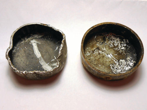
Distorted as this steel plug was, positioning it with a screwdriver to where it lined up as closely as possible with the casting hole, it appeared ready to come out. Unfortunately, when grabbing the plug with either the large and even medium Vise-Grips it was then too far off center. A small pair of needle nose Vise-Grips was used to line the plug up as close as possible. Their considerably smaller tips allowed the plug to be lined face a bit of a challenge. This happened to me with the casting plug located behind the starter. The plug didn’t tip as desired when it was driven inward and it went completely inside the water jacket. This wasn’t too surprising, after all in this case you’re working on your back on the floor, and even though the vehicle is elevated, the task has been complicated considerably. The same thing had happened with the plug on the opposite side of the engine, but it was easily retrieved with a magnet, and removed with Vise-Grips. So what happened this time? While the plugs are on opposite sides of the block, the locations are not exactly opposite, so the clearance inside was the next mistake, because it distorted the round shape of the plug making removal considerably more difficult. Photo 108 shows the plug that finally came out on the left, compared to one of the others that had been removed.
Once the round shape had become distorted, the battle was on. What should have taken a matter of minutes stretched into several hours. Had the plug been positioned inside the water jacket off to the right or left of the narrow area directly across from the cylinder, there would have been adequate room for the plug to be removed. Also, using the Vise-Grips in a horizontal position, the removal would have gone as smoothly
as the others. Back to the problem at hand; thoughts of using a Dremel tool and small cutoff wheel, or even drilling several holes in the plug to weaken it so it could be collapsed on itself and be removed were considered. These both seemed like ideas with merit, but now I was being cautious, wanting to make sure not to do something that would ultimately make the situation worse. Once either of those approaches was started, there was no backing out. Instead I kept moving the plug around inside the block and staring at it. A variety of larger and larger Vise- Grips with various jaw types and medium- to-large pry bars were being looked upon as the most likely to succeed in extracting the plug.
Distorted as this steel plug was, positioning it with a screwdriver to where it lined up as closely as possible with the casting hole, it appeared ready to come out. Unfortunately, when grabbing the plug with either the large and even medium Vise-Grips it was then too far off center. A small pair of needle nose Vise-Grips was used to line the plug up as close as possible. Their considerably smaller tips allowed the plug to be lined
up pretty close, and while holding it there, a small pocket screwdriver was used to tip out the edge the grips were holding onto. The small Vise-Grips were removed and a larger pair replaced them, a moment later the plug was out. Had there been a time schedule to keep, it was certainly out the window, and the frustration of the whole ordeal made me decide “it was the end of my broadcast day” as they used to say.
A few additional observations; had these casting plugs been very rusty and weak, the removal process would be different. Instead of tapping the plug inward, you most likely would be poking through it with the punch. Often in that case a prying tool can be inserted through the rusty hole, and leveraged against the block, popping the plug out much like removing an axle seal. Sometimes the weakened state of a rusty casting plug will make it easier to get out. Drilling a hole in the center of strong, solid plugs and using the pry tool method is another option for removal. This brings me to the fact that the plugs removed from the El Camino have all been in excellent condition. At this point the diagnosis of a leaking casting plug is highly in doubt. Remember while removing the knock sensor it was noted that it came out very easily? Well, the coolant leak was almost certainly coming from around its threads and being blown around, and not from the casting plug above it as originally thought. That plug was inspected closely, and looked great. All of this could have been avoided by cleaning the block in that area and using a pressure tester to spot the leak. Obviously it’s too late to back up and verify the situation now, but when all is back together, it will be pressure tested and observed. This is what happens when you go with instinct, making only a mental diagnosis
of what you think the problem is, and not verifying it with the proper test. One could view this as a total waste of time, but consider this. The temporary openings in the block will allow it to be flushed out with a strong blast of water from the garden hose. This will remove years of rust and junk that’s settled in the low end of the block that would otherwise be inaccessible. Ordinary bottle-type cooling system flush won’t touch this stuff. Besides, the casting plugs weren’t expensive, and a lesson was learned.
Rinsing Out the Block
In Photo 109 the garden hose is used to shoot a jet stream of water into one of the casting holes. Using the pressure washer was considered, but its 24”-long wand made it difficult to utilize in this situation, so the hose nozzle remained the best choice. The water stream is sprayed in different directions to try and loosen things up. As the water exits the rear casting hole, it eventually changes from a rusty color to clear.
To go one step further, a small bottle brush was inserted into the same casting hole as seen in Photo 110 and scrubbed around. Photo 111 shows the brush can reach fairly deep into the block. That side was then rinsed again, and then the same procedure repeated on the other side.
Additionally, the block was approached from the open rear casting holes. The bottle brush was of little use, not fitting in very well, and due to the elevation of the vehicle the stream of water chose to flow back out the same way it entered. Once the water was running clear, and I could no longer wipe my finger on the inside of the water jackets and emerge with a pasty rust substance, all was as good as could be expected.

Before replacing any casting plugs, the engine mounts still need to come out, and the decision must be made whether to replace those two remaining plugs.
In the meantime, an unusually cool Florida morning motivated me to replace those weak manifold studs. Maybe a momentary change of scenery would be a good idea.
Next, we’ll replace exhaust manifold studs, remove engine mounts and install some casting plugs.


