
Tackling Several Engine Projects Pt. 2
We Want to Replace Our Valve Stem Seals, But First Some Parts Need to Be Removed and We Have to Get the Cylinders and Valves In Proper Position.
Editor’s note: After putting many miles on his 1987 El Camino, the author knew the 4.3-liter V-6 engine needed some attention. So he decided to take on a number of repairs, including replacement of the intake manifold, replacing engine valve stem seals, replacing some casting plugs and installing new engine mounts. Last month he prepared for the project and removed the intake manifold. There were 15 images with the last installment, so we start here with Photo 16.
Sometimes the Distributor Can Be Difficult to Remove… Sometimes Not
This distributor had been removed not too long ago to replace its pickup coil, so it didn’t put up a fight this time. It’s typical to have to rotate the distributor back and forth while pulling upward. Older vehicles with a vacuum advance make this procedure easier, giving you somewhat of a “handle” on the side of the distributor to grasp.
The varnish build-up on the distributor housing and inside the engine is what you’re normally fighting. When this distributor was removed several months ago, it would lift up a bit and then stop. I would push it back down into the engine and then repeat the same movements again. The next time it would pull out a bit more. Even some WD-40 was used to help dissolve some of the varnish on the distributor housing.
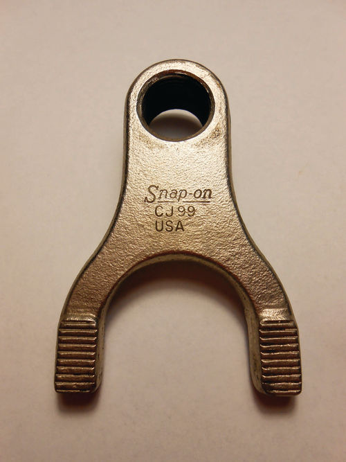
After working it several times, it finally let go of the engine. In my tool collection resides an old Snap-on adapter #CJ99 seen in Photo 16. It fits onto a slide hammer for removing stubborn distributors. Just the thought of that would make you wonder about the condition of the distributor once it’s removed. The older distributors with cast iron housings can withstand the impact much more than the aluminum ones. This tool will get the distributor out, but in some cases not without damage to the housing.
Continuing, the distributor cap and ignition wires can all remain in place and temporarily placing a rag in the bore for the distributor is never a bad idea.
So what’s left? The top alternator bracket must be removed. It bolts to the water pump, intake manifold and, of course, the alternator.
While in that area it’s a good time to remove the upper radiator hose as well as unplug the temperature sensor switch. There are still a few other wiring connections to unplug, such as the ignition coil and EGR solenoid. The ignition coil is mounted on the right rear of the intake manifold, just in front of the transmission fill tube. You can mark and identify these wires if you feel better doing so, but again the plugs are all application specific.
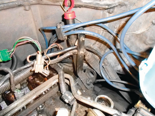
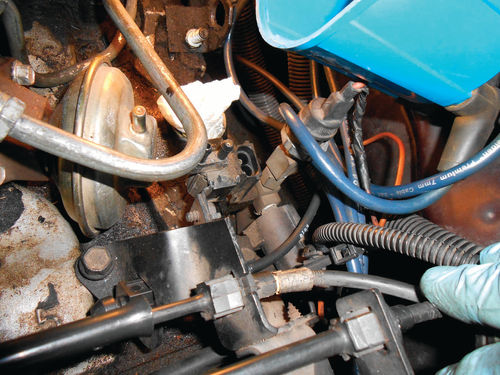
Remove the two coil bracket retaining bolts from the intake manifold and set the coil aside. Before leaving this area, there is a wiring support bracket seen in Photo 17 that will need to come off. The top wiring has come untaped from its plastic connector, but the lower one hasn’t. Squeeze those plastic ears together with pliers and then carefully pull the connection free. Now the bracket can be removed. In Photo 18 you are looking down at the bracket for all the throttle body cables, and behind the EGR valve is the EGR solenoid. Note that its wire connector has already been unplugged. The EGR solenoid bracket mounts over the top of the cable bracket on the rear. One bolt you can clearly see threads into the top of the intake, the other mounting is secured by one of the intake-to-head bolts. So removing these two bolts will free both the linkage bracket and EGR solenoid from the intake. When any brackets are removed, it’s a good idea to thread the bolts back into their locations. That will eliminate confusion later. It’s an excellent idea to loosen and remove the EGR valve at this time. Once the manifold has been removed, the EGR passage can be thoroughly cleaned, and the valve replaced.
Finally, it’s time to unbolt the intake manifold and lift it off. When doing so you will find a few of the retaining bolts are longer, or have a stud on the end for retaining brackets as you may have noticed in Photo 18, so pay attention and note their locations.
There’s Plenty of Dirt and Grunge
Before loosening any manifold bolts remove as much of the grease and dirt build-up as possible at the joining surfaces of the intake and heads. This area is a dirt magnet. Use a small stiff brush to loosen the grunge, and follow that with a shop vacuum to make sure it’s as clean as possible. (Note: If you use your shop vacuum for other tasks like vacuuming your vehicle’s interior, you will want to thoroughly clean its components once this dirty work is completed. The crevice tool, hose and vacuum itself will all need cleaning. For the hose and attachments that have been used, something like a large plastic trash can with a solution of Dawn dish soap and water work well for cleanup.)
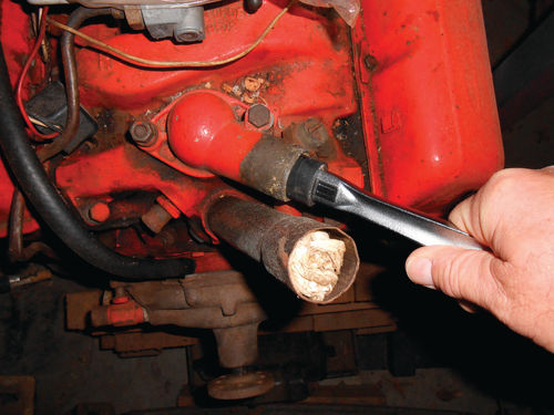
Once sufficiently clean, the manifold can be unbolted and lifted off. In this case that’s exactly the way it went, but sometimes the manifold may not want to let go so easily. In the days when everything was cast iron there was little concern if you had to pry on the manifold to get it loose; aluminum is another story. A point of leverage that seems fairly safe (as long as tremendous pressure isn’t applied) is the thermostat housing. With the thermostat housing still bolted securely to the manifold, stick something in the end of the neck for leverage, like the handle of a ½” drive ratchet and lift. It will usually release without too much effort. Cutting off a section of that old discarded heater hose and wedging it over the ratchet handle will yield a little protection for the thermostat housing. Photo 19 shows this procedure on an old 327, which is close enough to give you the idea.
Once the intake was lifted off, there were two observations to be made.
1. Yes, it does have roller lifters.
2. Boy, this engine is filthy inside. It was surprising to see how sludgy the oil valley was. The metal spring plate in the bottom of the oil valley that keeps the roller lifters positioned properly was unbolted for immediate cleaning and to give better access for cleaning things up. Photo 20 shows that paper towels have been used to fill the ports in the head. This will block any gasket scrapings from entering. Down below in the center of the oil valley towels have been used to cover the exposed camshaft and try and keep the sludge contained. There is still quite a bit of loose, hard sludge to be removed.
Some chunks of sludge were large enough to pick out by hand. The smaller stuff will be scraped and vacuumed. This engine has 225,000 miles on it, and has been running on synthetic oil since it was acquired with 113,000 reading on the odometer.
I am not going to go crazy and try any special heroic cleanup measures. The engine runs strong and quiet, and the thought of running some mystery solution in the crankcase seems scary. This sludgy condition, however, does raise the thought of removing the oil pan while the engine is elevated and cleaning that out. It too must have a layer of sludge in the bottom. This would also allow a look at the oil pump pickup. Most likely the pump would end up being replaced, especially if I’m replacing or cleaning the pickup screen.
It’s so easy for projects to grow and grow, just like a home remodeling project. There’s a fair amount of cleanup work to be done, as well as repainting items like the intake manifold, valve covers and possibly some of the brackets, but let’s leave that for now and continue forward with the repair projects on the initial list.
Valves and Valve Stem Seals… and the Importance of Being at TDC Compression
It’s time to focus on the valves and valve stem seals. The engine is already positioned with #1 cylinder on the TDC compression stroke, and that’s where we’ll start. The seals for both the intake and exhaust valves of the #1 cylinder will be replaced, and then those valves will be readjusted. Once they are done the harmonic balancer could be rotated one full turn clockwise until the timing mark is once again lined up on 0. The engine would then be on #4 cylinder’s compression stroke and both of its valves could be done.
So what about the other four cylinders, and is it absolutely necessary for each to be on the TDC compression stroke? By positioning each cylinder on TDC compression you are accomplishing several things. Compressed air can immediately be used to fill the cylinder as both valves are closed, and with the piston at the top of its stroke, it takes less volume of air to do so. Should the unexpected happen like an air hose or adapter failure (it’s happened to me), a power interruption to the compressor or even a compressor failure, the world won’t come to an end. Should a valve drop, it’s easily retrievable without having to remove the cylinder head. But if the piston is somewhere deep down in its bore, you know where the valves will end up. Also, introducing compressed air into a cylinder with the piston somewhere between the top and bottom of its stroke will usually rotate the engine and change the valve positions. Finally, being on TDC compression stroke means that both valves are also ready to be readjusted, and that cylinder can be checked off as completed.
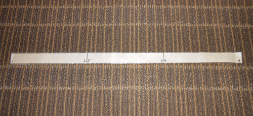
Create a Timing Mark Tape for the Other Cylinders
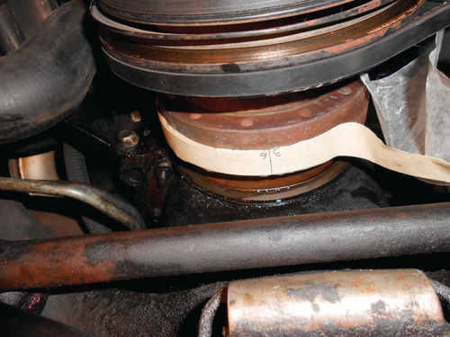
The method I use for determining TDC compression for the remaining cylinders is to create timing marks using a piece of masking tape. First a thin flexible tape measure is used to measure the circumference of the harmonic balancer. The timing mark notch is a good place to start and stop, however it will need to be rotated to a more accessible location such as straight down at 6 o’clock. This balancer measured 19 5 ⁄16”. Next measure and cut a piece of masking tape to the exact length, and then mark two lines on it, dividing the masking tape into equal thirds like the example seen in Photo 21. The harmonic balancer must be cleaned sufficiently so that the masking tape will stick to it. Then the right end of the masking tape will be attached to the harmonic balancer starting at the timing mark notch, and wrapped in a counterclockwise direction as shown in Photo 22. I put waxed paper over the last half of the masking tape to keep it from picking up dirt or sticking to itself. As the crankshaft is rotated clockwise, the waxed paper is pulled away and the tape pressed onto the balancer. Working from underneath it’s easiest to rotate the crankshaft using a 5 ⁄8” socket on the crankshaft pulley bolt. The left end of the masking tape should meet up again with the timing mark notch; if it doesn’t, there is an error somewhere.
As long as you know where you are starting from, such as #1 TDC compression, there is no question what’s next. Rotating the crankshaft 1 ⁄3 rd rotation clockwise to the first line on the tape will be the next cylinder in the firing order; in this case that’s #6. Rotate an additional 1 ⁄3 rd clockwise and that’s #5. Finally another 1 ⁄3 rd rotation clockwise makes one full revolution of the harmonic balancer. When the timing notch is lined up with 0 on the indicator, this is #4 TDC compression stroke. Both ends of the tape as well as each line have been marked with the cylinders they represent. Had this been an eight cylinder, the masking tape would be equally divided using three lines. If you are wondering how accurate these timing marks are, they’re accurate enough; probably within a few degrees is an educated guess. Once you have made and successfully attached the timing tape, it will save you time, and it’s easy to keep track of where you are.
An option to this method is to bring each cylinder in the firing order up on its TDC compression stroke by watching to see when both valves are closed, and then listening for air escaping its spark plug hole as the engine is rotated. Then use something to reach in and touch the top of the piston to verify it’s at the top of its stroke.

Using Compressed Air To Support the Valves Requires…
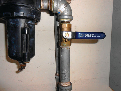
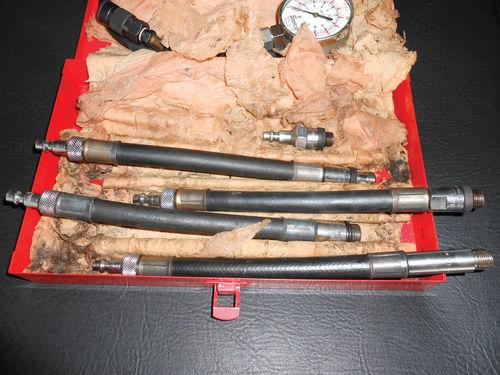
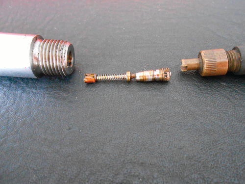
To maintain the valves securely in their closed position, compressed air is the most common method. So besides the obvious, what do you need? If you will be using any air tools at the same time a cylinder is pressurized, you will need a manifold connection to allow using more than one air hose simultaneously. A valve is needed to control the speed at which the cylinder is pressurized. Pressurizing a cylinder abruptly will most likely rotate the crankshaft, and you don’t want that. A lever-type ball valve works great for this task. They are inexpensive, available in many different sizes, and can be purchased at home improvement centers or hardware stores. Photo 23 shows one used in my air delivery system. A pressure regulator can also be used to perform this same task. But raising and lowering the delivery pressure this way will certainly be more time consuming. Most importantly, an air hose adapter is needed to thread into the spark plug hole. If you have a cylinder compression tester with interchangeable ends, or a cylinder leak-down tester, you likely already have an adapter that will work. Photo 24 shows some various adapters that are part of an old compression tester kit. They can also be used for pressurizing a cylinder to support the valves. The quick disconnect must be the same type as your air hose, so test to make sure. On these type tester adapters you will need to use a tire valve core tool and temporarily remove the valve core as seen in Photo 25. Set it aside in a safe place, and remember to reinstall it once this task is completed.
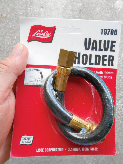
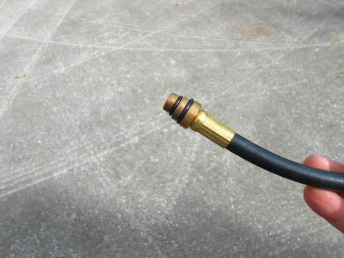
If you don’t have any adapters in your toolbox, don’t worry, there are plenty of inexpensive options. Online www.nationaltoolwarehouse.com offers two, one by Gearwrench, #KDT2992 called "air hold extension hose" for $8.95, and also one by Lisle #LIS19700 for$10.28 that appears to be almost identical. rockauto.com also offers the Lisle tool for $8.78, and www.amazon.com has it for $10.51. The Lisle product is seen in Photo 26, and it’s made in the US. It is designed (like most) to fit both 14mm and 18mm spark plug holes with the stepped double threaded end seen in Photo 27. Amazon also offers one by Moroso #62385. This kit has three interchangeable ends and a 12” adapter hose for $32.50.
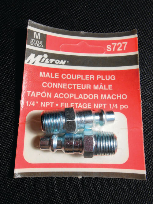
If you work with an auto parts store, the best thing is to first call around locally. For example, a check with Advance Auto Parts showed the adapter available online for $12.69, but not in their stores. Just to be sure a call was made, and indeed that was the case. It would have to be ordered. So planning ahead for this could save you some downtime. Regardless of where you purchase this special hose, it will require an adapter to fit your hose coupler. The Milton "M" style shown in Photo 28 could be considered the industry standard, but yours might be something different.
If Compressed Air Isn’t Available, There’s Another Approach
While I have never tried it, nylon rope is another option for supporting the valves with the cylinder heads remaining on the engine. You will find this information mentioned in the Haynes repair manual. “If you don’t have access to compressed air, an alternative method can be used. Position the piston at a point approximately 45° before TDC on the compression stroke, then feed a long piece of nylon rope through the spark plug hole until it fills the combustion chamber. Be sure to leave the end of the rope hanging out of the engine so it can be removed easily. Use a large breaker bar and socket to rotate the crankshaft in the normal direction of rotation until slight resistance is felt.”
Now, Back to the Compressed Air Method
So the #1 cylinder is at TDC compression, and that’s where to start. The adapter is threaded snuggly into that spark plug hole, and then the non-pressurized air hose is connected to the adapter. The regulator is set to 80 psi, that’s more than enough to hold the valves, and it reduces the cycling of the compressor. If you don’t have a regulator don’t worry, more pressure won’t hurt anything. The ball valve is opened very slowly allowing compressed air to enter the cylinder. As previously mentioned, if too much air is allowed to rush in quickly, the crankshaft will likely rotate. You will usually hear it when this happens, but just recheck the timing mark to be sure.
Once it sounds like the cylinder is full, open the ball valve completely. Don’t be surprised to hear air leaking, a certain amount is normal. If there’s a lot of air escaping you might consider moving to the next cylinder in the firing order and give it a listen for comparison. If one cylinder is leaking more than others, it may be an indication of mechanical problems, but not always. That happened to me not all that long ago with our 1986 Caprice. At 280,000 miles the original “nylon” timing gear let go. Sure, I knew better than to wait that long, but it was running decent and I absolutely forgot about it. Anyway, while replacing it, the valve stem seals (among other things) were also replaced. When the last cylinder was pressurized, a considerable amount of air could be heard escaping into the intake manifold. A few taps on the intake valve improved, but didn’t eliminate it. Evidently when the timing gear let go and everything spun around like crazy, some carbon came loose and found its way in between the valve and seat. With the valve spring removed, and air pressure released from the cylinder, a reciprocating valve lapping tool was connected to the valve stem and a few turns of its crank lever was all that was needed to correct the situation. So listen and be aware, the compressed air might be trying to tell you something.
Next, we’ll replace the valve stem seals.


