
Chasing down a hard to diagnose battery drain issue
Something as Small as a Wire Can Cause Big Problems. And It Took Detective Work to Find the Culprit.
AN EASY-TO-FIX little lamp was causing big problems with a collector car’s electrical system. Each time the car was used recently, the battery went down really low or died completely. The ammeter acted erratically, showing a correct charging pattern at some times and pegging itself to the (-) discharge side of the gauge at other times. Sometimes the car made it home fine and sometimes the battery went flat. Throughout the car, lights and accessories acted strangely.
When Checking for One Problem… Look for Others
To troubleshoot the problem, normal steps were taken. The battery was swapped for a known good battery of the same type and the same problems occurred. When fully charged, the battery was tested with a voltmeter, which indicated it was in good shape and putting out enough volts to start the car.
Normal meter checks were made of the generator and voltage regulator and both checked out OK at the time the tests were done. Several electrical connections were undone, cleaned up really well and carefully fastened back together.The car made a 15-mile trip to a cruise night without a hitch, but after a 15-mile trip to work the next day, it had to be jump started.
Next, the voltage regulator was replaced based on the idea that the old one might have been working on and off. As you might have guessed, the new regulator made no difference. The car still worked fine one day and not the next.
Noting that the taillights weren’t as bright as they should be and that the turn signals didn’t flash as quickly as they should, it was decided to take the taillight assemblies apart, check and clean all connections and grounds and make sure that everything was properly re-assembled. All of this was done. Some light corrosion was cleaned up. But everything still worked the same.
A Discovery While Shifting Gears
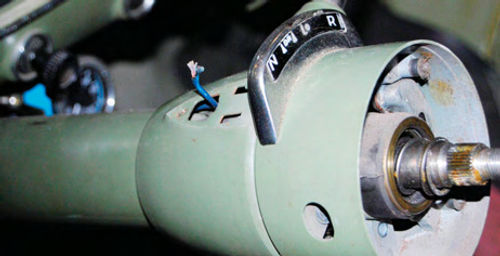
Then, while moving the gearshift lever from forward to reverse to check the backup lights’ operation, a funny thing was noted. The car—a 1953 Pontiac Catalina with four-speed Hydra-Matic Drive—has a chrome gear shift indicator on the upper steering column hub and chrome pointer on the separate upper mast housing that incorporates a bulb for lighting up whichever gearselection the car is in. In other words, when in neutral the “N” lights and when in Drive 1 the “D1” lights and so on. As The gears were changed, the “N” on the far left of the indicator lit up and the “R” on the farright lit up. However, none of the forward gear positions (“D1,” “D2” and “L”) illuminated when those gears were selected.
The consistency of this problem was tested by running through the gears several times and the same thing happened each time. Worse yet, when the chrome gear selection pointer was touched, it was hot!
While checking for correct backup light operation, a short in the indicator lamp had been discovered.
Understanding “Unordinary” Problems
To fix such a short it’s necessary to explore what parts are involved, how they work together and what it takes to repair them.
Ordinary problems with older cars, such as rough running, stalling, hard starting and ugly engine noises are usually covered in the factory shop manual. The manual probably has electrical schematics and some pictures of the upper steering wheel assembly. However, the manuals do not specifically cover some of the small wear-and tear problems that old-car hobbyists encounter. This shift indicator lamp fix is in that category.
Sometimes, the harder-to-find Master Parts Catalog will help identify a part needed to fix a problem. These books contain exploded views of various assemblies on cars. For this problem a 1955 Pontiac Master Parts Catalog was consulted, but unfortunately it did not show the parts of the 1953 Deluxe steering wheel. However, it illustrated two earlier wheels and gave us some idea of the parts involved, although it did not provide enough detail on the indicator lamp.
A used steering column for the same car was available in our spare parts bin and this proved very helpful. Although the steering wheel and upper mast assembly had been removed, by inspecting the rest of the other column it was clear that the wire running to the indicator lamp that is housed in the chrome pointer enters the steel column through a little door about halfway down the mast. This wire is then threaded up through the column to an opening in the upper mast housing where the chrome pointer is normally screwed on.
It was noted that the upper few inches of the wire in the used steering column had been replaced with a new wire. This made it clear that the wire in this area is prone to damage and wear. That’s not surprising. The top of the wire runs into a metal receptacle that holds a small light bulb inside the chrome pointer. Since both the end of the wire and the light bulb and light bulb holder move back and forth constantly as the gears are changed, wear is almost assured. It was likely that the wire in the car was worn or broken in this area. Looking at the used steering column also provided a good idea of what gauge of wire was required.
By the way, lacking a used steering column, a good way to understand what an “unordinary” problem with an old car entails is to join a car club that has technical advisors who are familiar with your type of car. The technical advisor should be able to give you helpful repair information beyond what you’ll find in the factory shop manual. Forexample, The Pontiac Oakland Club International (poci.org) does have technical advisors for the similar 1953 and 1954 Pontiacs. The Buick Club of America (buickclub.org) has actually published a complete book of technical tips for repairs that are not covered in Buick factory shop manuals.
Doing It the Hard Way
Without specific step-by-step shop manual instructions and working from the inspection of a used steering column that wasn’t complete with steering wheel and upper hub, the repair of this particular shifter indicator lamp went down a slightly longer road than proved to be necessary to make repairs. However, the extra steps that were taken did reveal some other problems with a sticky and slightly rusty horn mechanism. The horn repair, however, is a different topic for a different article while here we’ll cover the simpler way to fix the lamp.
The chrome gear shift indicator ornament that is marked with the various drive ranges attaches to the upper hub of the steering column. In normal use, it remains stationary and does not have to be removed to fix a broken wire or lamp assembly. The chrome pointer that moves back and forth attaches to the next lower section of the steering column. This is the part that moves when gears are shifted. It houses the gear shift indicator bulb and the bulb holder. Tabs on the pointer clip into “l” and “reverse L” shaped openings. Below these is a square opening that the wire comes through. Then a screw at the bottom attaches the chrome pointer firmly to the steering column.As soon as this screw was removed and the pointer lifted off, a broken wire was evident. The wire had completely separated from the metal receptacle that held a 6-volt miniature bulb.
This, of course, raises the question that if the wire had broken free, why did the indicator consistently light at the far right and far left positions?The “frame” of the gear indicator is made of metal (not plastic like it probably would be today) and apparently when the pointer moved all the way to either side, the lower part of the pointer hit a “stop” point against the metal frame. Thus, the wire had to be touching the frame and when the pointer hit either stop, it closed the circuit and lit the bulb.
Repairing the Bulb Receptacle
As mentioned, the upper few inches of the wiring on the spare, used steering column had been repaired by splicing a few inches of new wire onto the top end of it. This Repair was sloppy looking and didn’t seem to be the best way to go. It was easy to guess that the splice would tend to pull apart as the gears were changed over and over. A better way to fix the problem was to repair the bulb holder using a long pigtail wire and then run this wire down through the steering column to the door at the middle where the wire bundles came together.
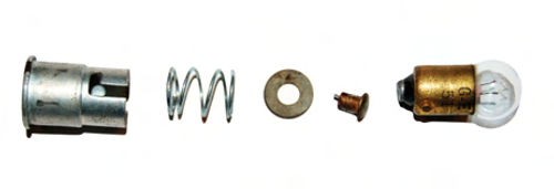
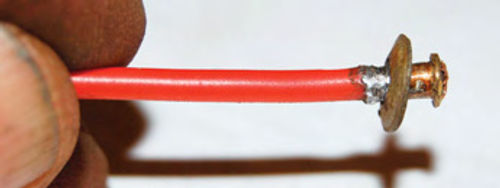
The bulb receptacle was simple and in good shape. There was no rust or corrosion on it. The wire entered through a hole in the rear, passed through a short spring, then passed through a fiber disc or washer. The tip of the wire (before it broke) had been soldered into a brass “button” that had a neck that went through the fiber washer. The wire had simply broken off the brass button.
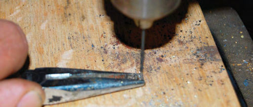
Using a small bit in a drill press and holding the brass button with needle nose pliers, the bit was lowered into the neck of the brass button so the old solder and broken off strands of wire could be removed from the neck. The tip of the drill actually went through the button, which wasn’t a problem. A piece of wire of the correct gauge for a 6-volt lamp was cut to about three feet in length and stripped clean for about a half-inch at both ends. One end of the wire was placed in the neck of the brass button pulling the end strands through the hole at the top of the button. A small gap was left between the red plastic insulation on the wire and the bottom of the neck of the brass button.
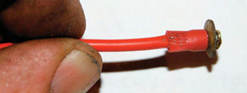
Using a very simple $1 soldering iron, solder was dribbled into the small opening between the red plastic insulation on the wire and the neck of the brass button. The solder was allowed to cool and then a small grinding wheel was used to make the shape of the solder glob the same as that of the neck of the brass button. When everything was the same diameter, the fiber washer was then run up the wire, over the solder and over the neck so that it was flush with the button.
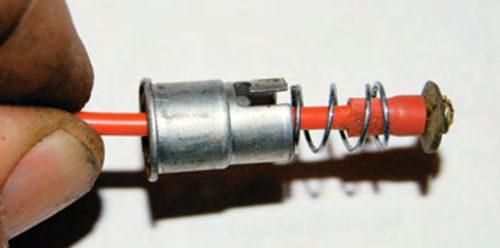
Since the grinder had removed a little more red plastic insulation than necessary, the red plastic collar was pulled off a standard “eye” type electrical connector and pushed up the pigtail wire and against the fiber washer. After making sure it covered the bare spot, the collar was crimped around the pigtail wire with needle nose pliers. The short spring was then run up the pigtail and against the bottom of the fiber washer. Then the light bulb receptacle was run up the pigtail and over the spring and the fiber washer was pushed down into it. Then the miniature 6-volt bulb was inserted in the receptacle and twisted in place. The receptacle has two slots that the nibs on the light bulb twist into.
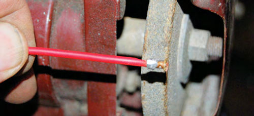
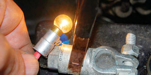
The repaired bulb receptacle looked good and felt tight. To test its electrical operation, the end of the pigtail wire was touched to the positive post of a 6-volt battery in a different car and the metal receptacle was touched to a screw on the car’s fender apron. The bulb lit and maintained a steady glow. It works fine and is ready to re-install in the steering column for years of trouble-free future use.


