
Restoring Mom's Car
The 1987 Park Avenue uses air- over-fluid struts in the rear and MacPherson struts in the front. At the more-complicated front struts, the shock absorber and coil spring are assembled as a unit. At the rear, the strut and spring are separate. Unlike shock absorbers—bolt-on parts that merely dampen spring movement— the Buick’s front and rear struts act as vital suspension structures. Moreover, replacing a strut at either the front or rear of the car requires realigning the wheels afterward.
At each rear wheel, I loosened two sturdy bolts holding the strut’s lower end to the knuckle (the casting to which attach the strut, wheel bearing and hub, and brake- backing plate). Likewise, I removed two nuts holding the top of the strut to a sheet- metal tower, accessible by removing the trunk’s side trim.

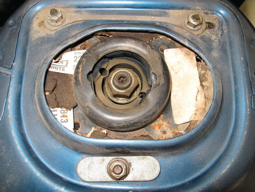
A visible rubber air chamber on each rear strut announces that the car uses Delco’s “automatic level control” system. Coupled with sensors and an under- hood air pump, the system automatically fills or deflates the car’s rear struts to compensate for extra passengers or luggage (Photo 14).
With the back of the car elevated and supported by jack stands, I placed my floor jack beneath the left rear suspension control arm, which doubles as the coil spring’s lower seat. By lifting the control arm slightly, I lightly compressed the coil spring to keep it from popping free when I disconnected the strut. I freed the strut by removing two bolts (lower end) and two nuts (upper end).
Removing a Strut Saddle
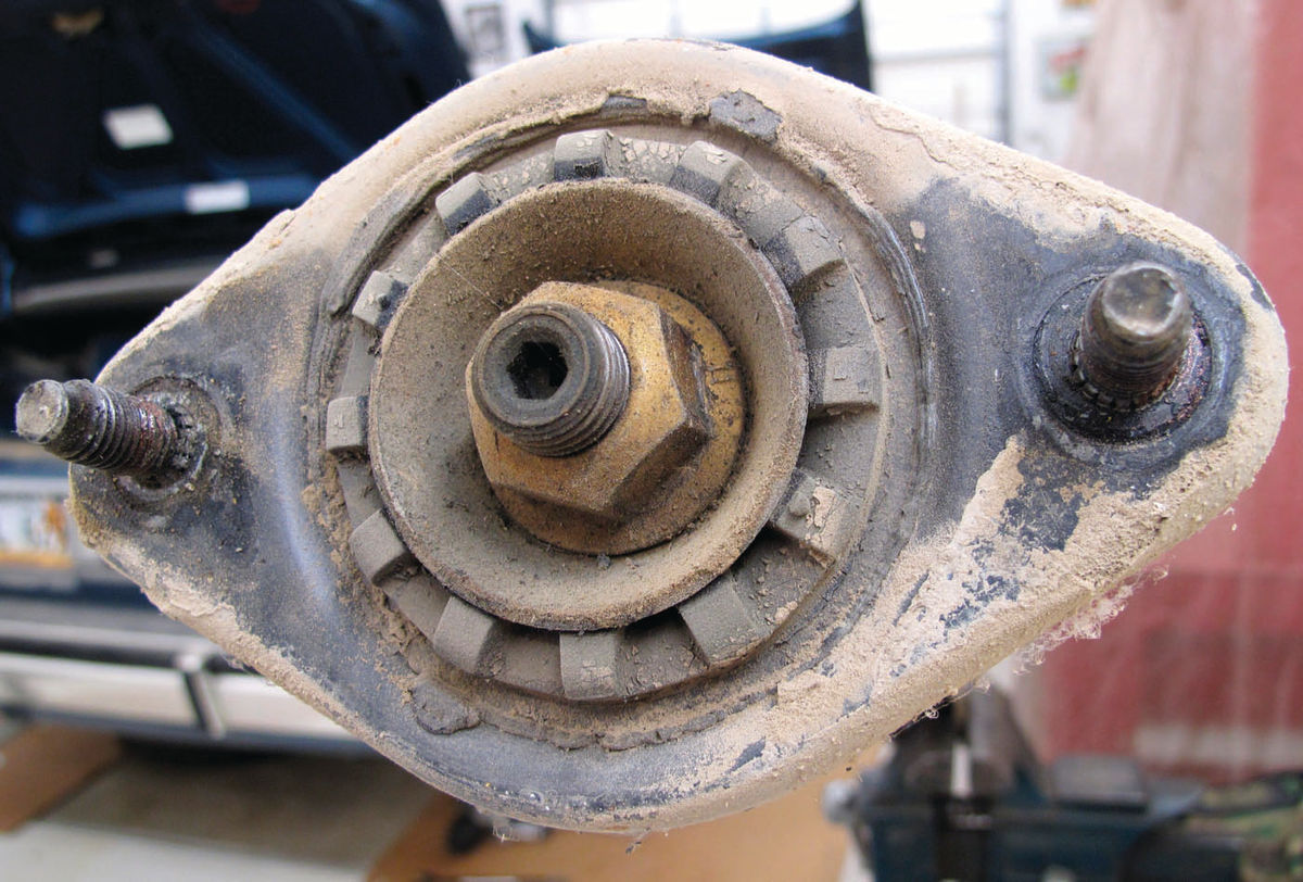
I disassembled the top of the old strut by unscrewing a large nut that attaches the strut shaft to a metal-and-rubber saddle (Photo 15). The easy way to do this is by using an air-impact wrench and socket to spin off the nut in a jiffy. This can spin the shaft and damage its seal, however, so use an impact wrench only when you plan to replace the strut.
If you plan to reuse the strut, you’ll have to disassemble its saddle the hard way: 1) Hold the top of the strut shaft with a hex key (or wrench, if the shaft has two flats ground in it) and 2) spin off the nut using a large boxed-end wrench.
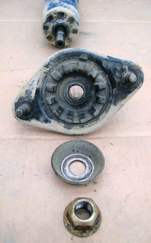
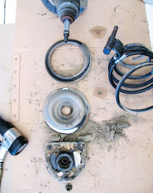
After disassembling the top pieces, I laid them out and snapped a photograph to ensure that I’d reassemble the parts correctly. Because factory shop manuals often cover many different models, your strut assembly may contain more, fewer or different parts than the strut shown in the manual’s “typical” view (Photo 16).
Cleaning Nuts and Bolts
I cleaned all the reusable fasteners in my solvent tank, which included holding each nut in a Vise-Grip and running a drill-
mounted cylindrical wire brush through its internal threads. Next, I clamped each bolt in a Vise-Grip so I could thoroughly polish its threads and the rest of it at a floor- mounted wire-wheel buffer. You’ll never correctly torque a nut or bolt if the threads are dirty or rusty.

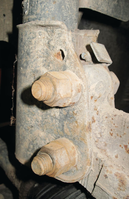
The cleaning continued at both rear wheels, where I once again used a drill- mounted cylindrical wire brush to remove rust and dirt from the two strut-mounting holes in each knuckle (Photo 17).
For safety, the floor jack placed beneath the control arm should remain there until you finish installing the new strut. Attach the new strut’s upper saddle to the car’s shock tower and finish the installation by raising or lowering the floor jack slightly to align and install the new strut’s two lower anchor bolts.
I bypassed the car’s automatic level control, partly to postpone repairing the air pump and partly because new air struts cost twice the price of standard fluid-filled rear struts. It’s a common conversion and a reasonable one, given that I use Parkhurst for simple transportation, not hauling.
I used nylon zip ties to double over the free ends of the air lines that normally attach to nipples on the struts. I also sealed the air lines with plumber’s putty (duct seal) and pulled the air pump’s 20-amp fuse.
Two Precautions Up Front
Removing the Park Avenue’s front struts involves unscrewing three nuts from the top of each one; two large bolts at the bottom and a single bolt attaching a brake-hose bracket (Photos 18 and 19). Because the shock and front coil spring are integral in a strut, there’s no need at this point to worry about the spring rocketing into orbit. That danger comes later. But two precautions are in order. One, protect the drive axles’ outer constant- velocity (CV) joint boots, which are nearby and easy to tear. I used bungee cords to wrap mine with corrugated cardboard. Two, block the lower control arm as you remove each front strut. Why? Each of the Buick’s two front control arms supports not only a heavy cast- iron steering knuckle and integral wheel bearing and hub but a brake rotor, caliper
and the outer end of a drive axle. Without a strut to suspend it, these control arms will drop precipitously, possibly damaging the drive axle’s CV joints. A special tool will compress the coil spring so you can place it on a new strut. Never try to disassemble a strut without compressing the coil spring or, yes, you will unleash a powerfully dangerous force.
Using a Spring Caliper
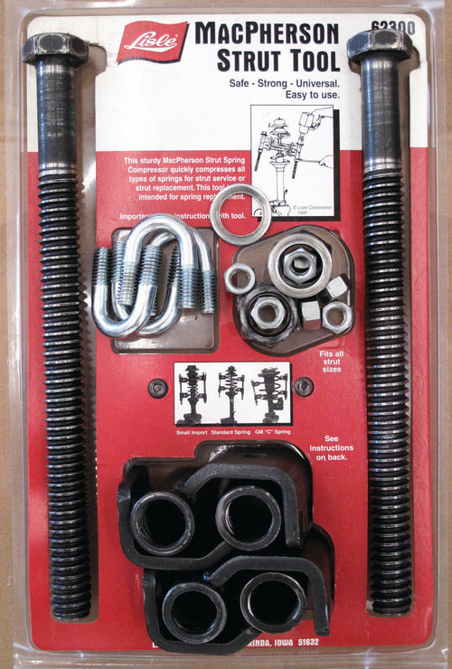
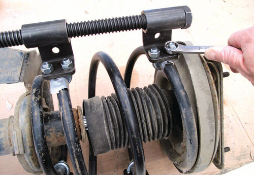
My arsenal includes a Lisle 62300, a twin-arm coil-spring compressor designed for use with an impact wrench (Photo 20). After assembling the Lisle tool’s two hardened bolts to the spring, one bolt on each side, compressing the coils takes only a moment with an impact wrench—far faster than by using a manual spring-compressor tool (Photos 21 and 22).
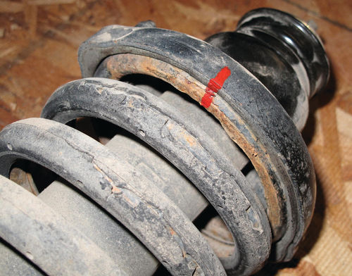
While disassembling the Buick’s front struts, I should have placed an alignment mark across the uppermost spring coil and the saddle as I did during an earlier project with a Honda (Photo 23). These parts must properly align during reassembly so the studs atop the saddle mesh with holes in the sheet-metal shock tower. In this case I resorted to time-consuming trial and error to realign the parts correctly.
I delayed installing the new front struts because their absence gave me extra room for making other front-end repairs. This work included replacing the steering tie- rod ends, ball joints, front wheel bearings and drive axles.
Turning to Tie Rods
I dealt first with the tie rods. In bygone days when all cars had manual steering, a long tie rod spanned the distance between the left-mounted steering gear and the right front wheel.
Nowadays, the amidships steering gears found on many front-wheel-drive autos have short threaded rods—still called tie rods—on either end. The tie- rod end is simply a spin-on ball joint that permits you to steer the car while the suspension is in motion.
Tie-rod ends also figure into the third component of a front-end alignment: caster, camber and toe-in. By cinching down a lock nut during an alignment, a technician will position each tie-rod end just so on its threaded tie rod to set the correct front-wheel toe-in.
Do-it-yourself articles and You Tube videos often advise freeing tie-rod ends by banging away directly on the joints or associated castings. It can work. I once gently tapped on the steering knuckles of a newer Honda and the tie-rod ends sprang free as if by magic. For any joint that has seen decades of rust, however, forget the Stone Age techniques.

Photo 24 illustrates a more precise way to go: a front-end service kit. The five pullers in this K-D Tools No. 41690 kit, which cost $86 including postage in 2011, will remove almost any Pitman arm (attached to steering gears), ball joint or tie-rod end.
A Tie-Rod Puller
Ball joints and tie-rod ends have tapered studs to fit tightly in tapered holes. A castellated nut and cotter pin further guarantee that such joints won’t pop loose while you’re driving.
Rusty cotter pins are almost impossible to remove from a car Parkhurst’s age or older. Thus I simply snapped off both ends of each cotter pin so I could fit a socket over the hardened castellated nuts, which pulverized the remnants of the soft cotter pins without damaging any threads.
I next followed these steps to remove the tie-rod ends at the Buick’s left and right front wheels:
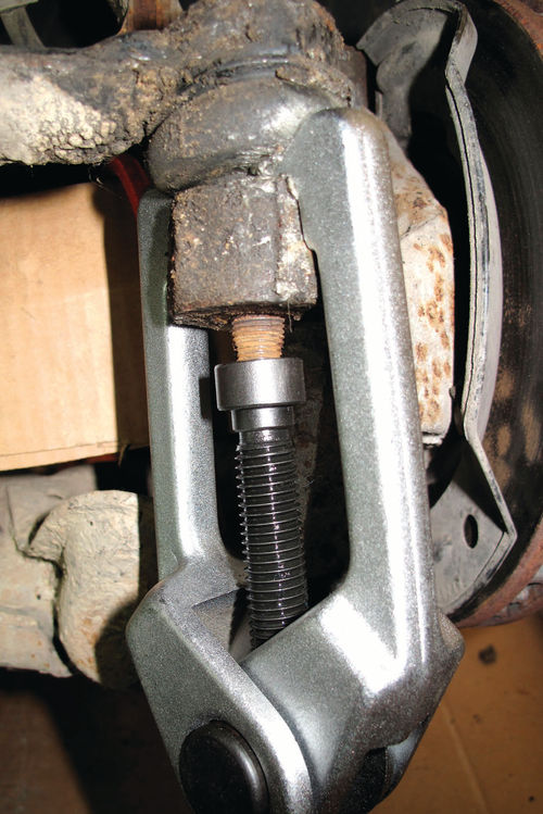
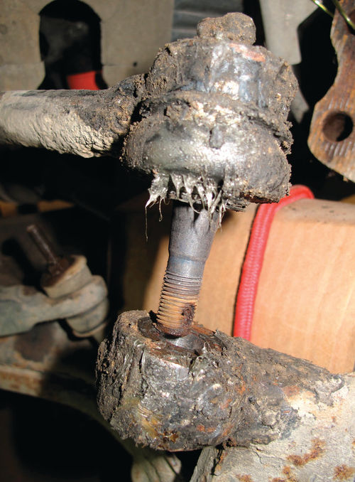
1) I freed the tie-rod end from the steering knuckle using the appropriate puller (Photos 25 and 26). If you plan to reuse the tie-rod end, screw on the nut, castellated end first, until it is flush with the end of the tapered stud. The nut will prevent the puller from mushrooming the stud.
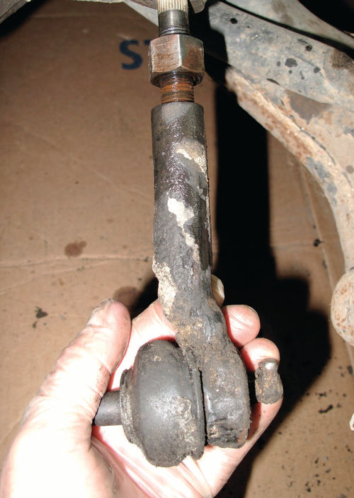
2) Loosen the tie-rod end lock nut with an open-end wrench. To provide an opposing force and prevent the shaft from spinning, slip a wrench over the flats cast into the tie-rod end. Now remove the tie-rod end (Photo 27).
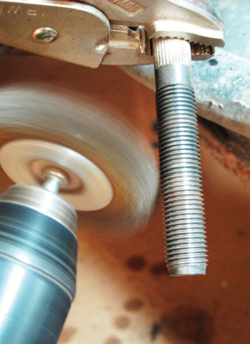
3) New tie-rod ends usually come with a new castellated nut and cotter pin. You’ll have to reuse the lock nut, however. Use a drill-mounted cylindrical wire brush to clean its internal threads. Chuck another style of wire brush in your drill to buff up the tie rod’s threads (Photo 28). Lubricate all threads with anti-seize compound to make the next disassembly easier.
4) To finish, I locked the new end to the tie rod in the exact same place as the old one, based on prior measurements. This gets your front-wheel toe-in close enough to drive to an alignment shop. I’ll reconnect the tie rods to the steering knuckles after finishing other front-end repairs.
Looking Backward
Here I took a break from suspension repairs to reattach the inside rearview mirror. Specifically, I loosened a set screw to separate the mirror from the metal mount that gets glued to the windshield.
Next, I used tape on the exterior to mark the correct mounting point (Photo 29). With this target in place, I scraped old glue from the glass and metal mount and cleaned both with alcohol.

Following directions in a mirror-re- sticking kit (sold at auto stores and even Walmart), I applied an activator to the glass, a drop of the glue to the mount and then pressed and held the mount to the glass for two minutes. I attached the mirror four hours later and haven’t looked back since.
Next time, Curt will revive the front end by replacing ball joints and installing new wheel bearings and drive axles.


