
Tackling Several Engine Projects, Pt. 1
You Know How It Is…the Engine Runs But There Are Necessary Repairs Calling for Your Attention. Now’s the Time to Take Care of Them.
For some time now I have been driving our 1987 El Camino realizing that there were several problems needing attention with regard to its 4.3L engine. Overall it drove well enough so naturally these needed repairs were pushed aside (you know the squeaky wheel theory) in favor of other projects, both automotive and with life in general.
When working on a spark knock problem some time ago it was discovered that a casting plug (some people also refer to them as core plugs, expansion or freeze plugs) near the engine’s knock sensor was leaking. So that’s one chore on the list, replacing the casting plugs.
With the engine in the vehicle, replacing any of the casting plugs wouldn’t be considered easy due to components such as engine mounts, the power steering pump, AIR pump, and possibly even the starter getting in the way.
Coincidently, the engine mounts need replacing anyway. If you try to make a jackrabbit start, especially when pulling a load, you can feel the engine rise momentarily, and then make a subtle thump when it again settles back down. This can also be felt in reverse if you quickly step on the accelerator, indicating that both the right and left mounts need replacing. So this is the perfect time to replace them, as they will both be removed for access to casting plugs.
There also are two casting plugs located on the rear of the engine block. To replace these either the engine must be out of the vehicle or the transmission removed. Seeing as none of the repair projects on my list require engine removal, pulling out the transmission would definitely be the logical choice. While being a firm believer that if one casting plug is leaking, the others can’t be far behind, removing the transmission is a bit much if those plugs appear to be dry. Besides, transmission removal isn’t required, nor does it make any of my other repair projects easier; that is, unless the engine’s rear main seal is discovered to be leaking.
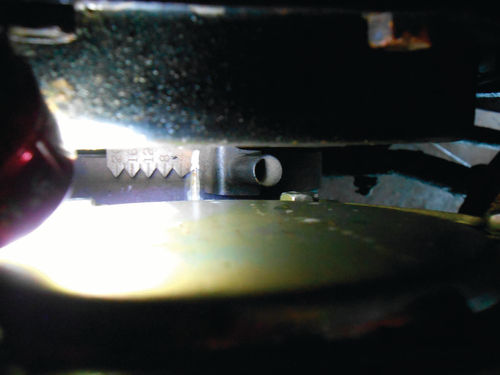
To inspect these two rear casting plugs, the transmission torque converter cover will be removed to try and get a peek at them. This is an extremely difficult location to see as you are trying to sight in between the flex plate and the rear of the engine. To aid in this task an automotive video scope (often referred to as a “Bore scope”) will be used. Its long optical neck should allow us to get up close and personal, and images can be viewed and saved to a mini secure digital (SD) card.
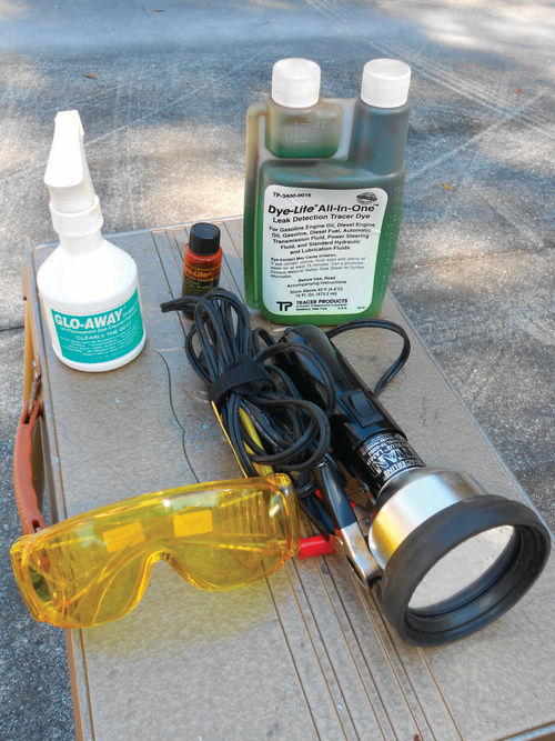
Additionally, if needed, a special dye can be added to the cooling system that will make any coolant leaks show up as a bright yellow liquid when using a UV light. This will make spotting any leakage in this very confined area considerably easier. The system I am referring to is the Tracerline leak detection system shown in Photo 1. They make dyes for finding leaks in oil/hydraulic, cooling, and A/C systems and likely there are other uses as well. In this case the appropriate dye is added to the cooling system, and the engine run until it is warm and the thermostat has opened. Once the coolant has had some time to circulate, turn off the engine and allow it to cool enough to where you can safely and comfortably work around it. Any system leaks will brightly fluoresce under the UV light.
This tool was purchased decades ago, and since then the prices have dropped considerably. I wouldn’t be surprised if this is in part due to country of origin, but that’s only a guess. Today you can find kits starting for around $50. www.mechanicstoolwarehouse.com offers an excellent selection, and they have an entry level kit #TP8621 currently priced at $48.
One problem that has worsened with the El Camino is the vehicle puffs blue smoke out the tailpipe during the initial morning start-up. Over time this has become more and more visible, and now is easily seen when looking in the rear view mirror. This is typical of leaking valve stem seals. Recently it reached the point that enough oil was entering one of the cylinders overnight that during the morning start-up it would momentarily foul one of the spark plugs causing a skip in the engine for about 30 seconds before smoothing out.
After the initial morning start-up, the engine performs well throughout the day. If the engine has been shut down for several hours you might notice a small puff of smoke, but no engine skip. Allowing this problem to continue is not environmentally or economically sound and will eventually lead to failure of the catalytic converter as well. So replacing the valve stem seals and checking to make sure the valve guides are not excessively worn is definitely a priority.
Finally, the intake manifold appears to be allowing oil to leak out the rear, so those gaskets will be replaced but to be on the safe side, the UV leak detector will also be used to check for any other oil leaks. You wouldn’t want to walk away thinking all was done only to discover a rear main seal leak, or seepage around the oil pan.
So at the moment the list looks something like this:
1. Remove and replace the intake manifold and replace gaskets.
2 Replace the engine valve stem seals.
3. Cooling system: replace the engine’s front and side casting plugs, inspect the rear plugs and use the UV leak detector if there is any uncertainty, flush the cooling system and renew hoses, thermostat and antifreeze.
4. New engine mounts.
5. Check for any additional oil leaks.
With all this work, where to start is just a matter of preference. There is some overlap in many of the tasks. Things like draining the radiator will need to be done before removing the intake manifold. Carry that to the next level by draining the block to avoid possibly taking a bath in antifreeze and having it splash everywhere when removing the casting plugs. And as previously mentioned, the engine mounts will need to be removed to access a couple of those casting plugs. Naturally the engine will need to be raised to remove the mounts, and the distributor cap is close enough to the firewall that it will need to be removed to avoid accidental breakage while the engine is elevated. Regardless, disconnecting the negative battery cable is a good thing to get out of the way. It could wait until later, but doing so now eliminates the possibility of overlooking it.
Starting the Projects
The decision was made to start by removing the valve covers and intake manifold, and then proceed with replacing the valve stem seals. (Note: You don’t need to remove the intake manifold if you’re only replacing the valve stem seals). These seals will be replaced with the heads on the vehicle, and compressed air will be used to fill each cylinder and support the valves during the process. The spark plugs will need to be removed to do this, and removing them now will make rotating the engine easier. No mystery here, just make sure to twist each ignition wire boot back and forth a few times to break its bond with the spark plug. If you don’t, the boot and/or ignition wire will very likely be damaged.
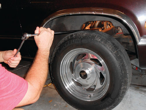
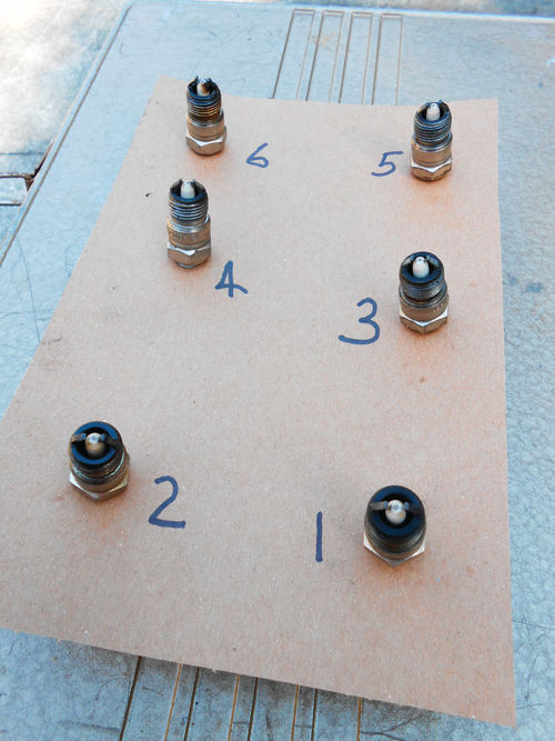
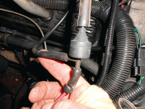
On the driver’s side of the engine a stubby extension was used with the 5/8” spark plug socket and a long 3/8” ratchet to remove all the plugs. On the right side it’s considerably easier to lift the vehicle up by the frame, allowing the wheel to drop down out of the way. Now, using an extra-long extension as seen in Photo 2, reach in through the wheel well over the tire to remove the plugs. It’s never a bad idea to record each spark plug’s location as it’s removed. A piece of cardboard with holes poked in it is the perfect organizer. Number each spark plug with the corresponding cylinder as seen in Photo 3. This allows you to study and get a read on each plug. If something is spotted, you know which cylinder may be having a problem.
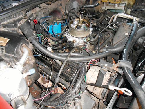
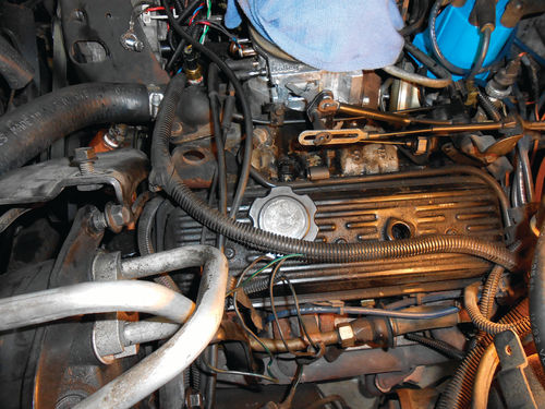
Photo 4 is a view of the engine with the air cleaner housing removed. While it could certainly be worse, you can see there are a number of obstacles before the valve covers and manifold can be removed. When the time finally arrives to start replacing the valve seals, each cylinder will need its piston at top dead center on the compression stroke. The normal procedure when removing the intake manifold is to position the #1 cylinder at TDC on the compression stroke, so let’s start with that.
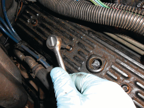
As shown in Photo 5, a ½” drive ratchet and 15/16” socket can be used on the alternator nut to rotate the engine. Slight downward pressure on the belt keeps it from slipping. Two screws retain the distributor cap; remove them and note where the rotor button is pointing. Note that these screws can easily fall out of the cap when it’s tilted out of the way, so be alert.
A Few Basics to Consider
When viewed from the front of the vehicle the engine’s crankshaft rotates clockwise while running, and its firing order is 1, 6, 5, 4, 3, 2. The intake manifold shows each cylinder’s number on the corresponding port. The #1 cylinder is the first (closest to the radiator) on the driver’s side, followed by #3 & #5. The even-numbered cylinders are on the right side starting with #2. (Sure, most readers know this but it doesn’t hurt to mention it. It should also go without saying that you need to have your vehicle’s service manual on hand.)
While it’s not absolutely necessary, I prefer to do all the “positioning” in the same direction as normal engine rotation. Naturally, if the distributor has just passed the #1 cylinder the engine can be rotated backward to reach TDC, I simply back it up beyond that point, and then go forward in the direction of normal engine rotation until it’s on target. This will likely never be an issue or make a difference, but it eliminates any backlash that might be encountered in reverse engine rotation, and is a good habit to acquire.
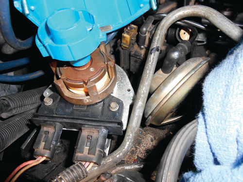
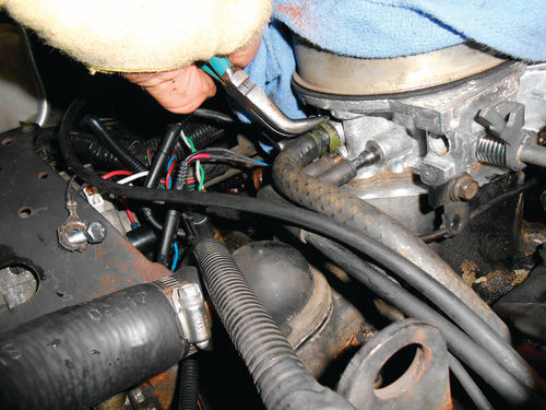
On this vehicle the timing mark is sighted by viewing down in between the timing cover and the back of the water pump. I have marked both the notch on the harmonic balancer and the degree indicator with a line of white paint. Photo 6 shows it’s lined up on 0°, but this could be on the compression stroke for #1, or the compression stroke for #4. A look at the distributor rotor’s orientation in Photo 7 indicates it is pointing toward #1. You might notice there is a reference mark made with a black Sharpie on the steel fuel line. The angle at which the photo was taken makes it look as though it’s not very accurate, but that’s not the case at all. A second reference is made between the distributor housing and the same steel line. In the photo it appears there is very little room to rotate the distributor counterclockwise before it will hit the steel fuel line. In this case the photo is giving an accurate representation. Using a 1/8” drill bit held vertically as a makeshift feeler gauge, it can just pass in between the fuel line and the distributor. Now I wouldn’t use it to set my timing, but from previous experience it will get it pretty close.
Obstacles and Reference Notes
If you look back at Photo 4 you can see that the heater hoses present a small obstacle for the right valve cover removal. These hoses are to be replaced anyway, so now is a good time to get them out of the way. Start by draining the radiator. This radiator has a drain valve, so that’s quick and easy. Had it not, carefully removing the lower radiator hose is the next choice. This will also drain a bit more out of the radiator.
As has been mentioned in my articles before, don’t leave antifreeze lying around in an open drain pan. Pets/ animals are attracted to it, and if they drink it, it can kill them. Use whatever is handy; old milk jugs are a good choice, and take the spent solution to your local recycling center. Some parts stores advertise that they accept old antifreeze, so make a phone call or two and find your closest option.
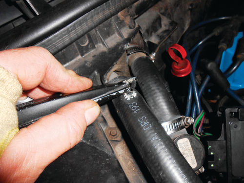
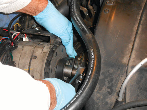
The heater hoses are being replaced, so cutting them at the heater core connections is the best way to avoid any possibility of damage. The tubes themselves are soldered to the core, and if you’re not careful, the solder joint can be broken. If this happens, the heater core will require replacement. Photo 8 shows cutting a slice through the side of the heater hose which cuts through the reinforcement cord. Once completely cut through, the hose will lose its grip on the tube, and can easily be removed.
On the engine side of things, you don’t need to be as concerned with “delicate” connections. Both hoses return to solid metal connections. While slicing the hose as shown in the photo will work just fine, you can just as well use a hose removal tool to break the bond between the hoses and their fittings. Hose removal (pick-type) tools are a must if you intend to reuse hoses.
A number of vacuum hoses will need to be disconnected. Make sure to identify where each hose connects by either making a map, tagging hoses and their corresponding locations or both. Additionally note how the hoses and wires are layered. This is most easily accomplished by taking a bunch of photos from various angels. You can almost be certain that the photos you don’t think you need will end up being the most valuable. It happens to me frequently, so take plenty of them. This way if there is a question whether a vacuum hose or wiring travels over or under the heater hoses, it can be verified via photos, and the proper appearance will be maintained. The “T” connections, like that seen in Photo 9, should be clearly noted so there isn’t any confusion when it’s time for reassembly. The large vacuum hose connecting to the top is the supply vacuum from the manifold; the hose exiting off to the left goes across the front of the engine and over to the left fender well where it then tees off and connects to both the vacuum storage sphere and cruise control servo. The “pinkish” colored vinyl line exits the bottom, and disappears off behind the A/C accumulator.
Valve Cover Removal
This clears the path to remove the right valve cover. A Torx T30 drive is used with a ¼” drive ratchet to remove the three retaining bolts as seen in Photo 10. The cover can then be lifted up and pulled forward toward the alternator for removal. Over on the other side remove the PCV hose and valve from the cover, and then disconnect the other end of the hose from the throttle body as is being done in Photo 11. There is a metal clip just above the valve cover that holds the hose. Twist and remove the hose from this clip. Once removed, inspect the hose for internal restriction; also check to see if has become rock hard, or even mushy. If it is questionable, replace the hose. Note, this is a preformed molded hose, and most certainly won’t be an in-stock item. The A/C Compressor has a support brace that angles down from the top compressor bracket to the intake manifold. If you go back and look closely in the upper right corner of Photo 4 you might notice it. Removing a couple of bolts gets this out of the way. The brace isn’t symmetrical so making a note of which end goes where will save you a moment or two when it comes time to reassemble. On this vehicle the slotted end mounts to the compressor bracket. Removing a total of four bolts will free the compressor from its mounting brackets. Once out, you can thread the bolts back into it, and position it so that it gives a bit more access to the valve cover as seen in Photo 12. Pay attention not to support the compressor by the aluminum connecting manifold, as refrigerant leakage or damage could occur.
Look closely and you might notice there is a steel vacuum line coming off the intake manifold, just forward of the oil fill cap, and running rearward, parallel with the valve cover. This is the supply line for the power brake assist (booster). A ¾” wrench is used to retain the manifold fitting, and a 5/8” flare nut wrench to loosen the steel line. This allows the steel line to be moved out of the way. Once the three retaining bolts are removed from the valve cover, pulling it toward the windshield and up will get it out. The wiring contained in the black plastic loom is simply pushed out of the way while the valve cover is lifted off. Working around the wiring is somewhat of a pain, but it’s doable, and besides there is no easy option. The valve covers are then set aside to be cleaned and painted. The rubber grommets in both valve covers are rock hard. Both the PCV valve and breather pipe require the same grommet. These aren’t flat grommets; they have a wedge shape to them. A trip to Advance Auto Parts was unsuccessful as the parts clerk could only find ordinary flat-type grommets. These will fit the older 1960s Chevrolets I own, but they aren’t correct for this vehicle or for that matter my ’86 Caprice. If there were nothing else available, the flat type will fit, and likely do the job, but the stress of the breather pipe being pulled inward will greatly shorten the life of the right-side grommet. A visit to NAPA came up with the correct grommet. Photo 13 shows a side view of it. Their part number is 630-1043, and the cost was less than $4 each. Another handy resource, www.rockauto.com, is good for purchasing parts and also for looking at images for comparison. They almost always show photos of the parts you are searching for, and while their images might not be a 100%-correct representation all of the time, they usually are. Even if you don’t want to mail-order parts, you can use their references to establish the needed part number. For example, this grommet would be a Dorman #42062, or Standard #GV9. After the cleaning and painting are completed, the new grommets will be popped in.
Time to Remove the Intake Manifold
The valve stem seals can be replaced without going any further, but the intake will be coming off anyway for gasket replacement, and sometimes it’s helpful to be able to see the valve lifters. Besides, the manual surprised me when reading through it. The cold valve adjustment procedure which will be discussed later states “3/4 additional turn (beyond zero lash) for roller lifter V6.” This is the first 4.3L engine I have owned, but just assumed it had flat lifters like the 5L “H” code (OK, a 305 CID) in the 1986 Caprice. Another quick visit to Rock Auto Parts shows the 1987 4.3L lifters as all being roller type. Being curious, the application for a 1986 El Camino with the 4.3L was checked, and that year shows (mostly) flat lifters. So what if this vehicle for some reason had an ’86 engine in it? Most likely someone who has worked frequently with these engines might be able to know for sure by just looking at something like the valve covers. The engine number could also be checked. The logical choice here is to simply continue on and remove the intake, and there will be no question.
The throttle body has several vacuum hoses needing to be disconnected; the one on the rear of the throttle body connects to the manifold absolute pressure (MAP) sensor that mounts to the side of the air cleaner housing. If you go back to Photo 4 and look closely, you might notice the MAP sensor standing there in front of the red transmission dipstick handle. Twist the hose loose from either the throttle body or MAP sensor, and unplug its wiring. Getting the sensor out of the way reduces the chance of it being damaged. Another look at Photo 11 shows there are several vacuum hoses below the PCV hose that will require disconnecting.
Revisiting Photo 12 you see the three linkage cables on the side that must be disconnected. The accelerator and cruise control cables are retained with clips, while the lower mounted transmission cable disconnects by simply pulling its connector toward the radiator. It will snap free of the connection post.

On the opposite side unplug the two electrical connections. Each of the electrical plugs is fitted specifically for its application, so there is no confusion here. The wiring to the injectors must also be disconnected. If you followed my series on spark knock (AR December 2014-March 2015) you may recall this is a Holley replacement throttle body, and I used two lead universal trailer connector plugs for an external disconnect. Had this still had the original Rochester throttle body, the connectors would be unplugged directly from the two injectors. Now all that remains is to disconnect the two fuel lines and three throttle body retaining bolts. The throttle body and gasket can be lifted off and set aside. The two open ports are plugged with a couple of towels to avoid anything entering the intake. Photo 14 shows how things look at the moment.

Next will be the distributor. First unplug the two wiring connectors from the distributor module, and then use a 9/16” wrench to loosen and remove the retaining bolt and clamp. More specifically I used the 9/16” distributor wrench you see in Photo 15. No, this isn’t absolutely necessary, but it certainly makes life easier. There are universal distributor wrenches, and some are actually vehiclespecific. This one is a Mac #S 105, and has been in my toolbox for close to 40 years. Obviously, it’s not specific for this vehicle.
Next time: After we remove the distributor, we’ll deal with some “dirt and grunge” and focus on the valves and valve stem seals.


