Tackling Several Engine Projects Pt. 5
This Time We’ll Install the Distributor and Make Sure It’s Properly Oriented, Route Some Wiring and Vacuum Hoses, and Clear Paths So We Can Get at the Casting Plugs.
Editor’s note: The author has been performing a series of repairs on the 4.3-liter V-6 engine in his 1987 El Camino. Most recently he did some valve adjustments, painted some parts and replaced the intake manifold and the TBI. We’ve had 69 images in the series so far and will be starting here with Photo 70.
Replacing the Distributor
With the TBI now bolted in place, and more specifically its fuel lines connected, the distributor rotor reference mark (made with a Sharpie on the steel fuel line) has returned. So installing the distributor will be next on the list.
The engine is set on #1 TDC compression, right where it was when the distributor was removed.
When replacing the distributor there are several things to note: Don’t forget to put the base gasket on the distributor housing. Next you want the rotor to end up pointing toward the #1 terminal in the distributor cap, and the distributor housing to be properly orientated.
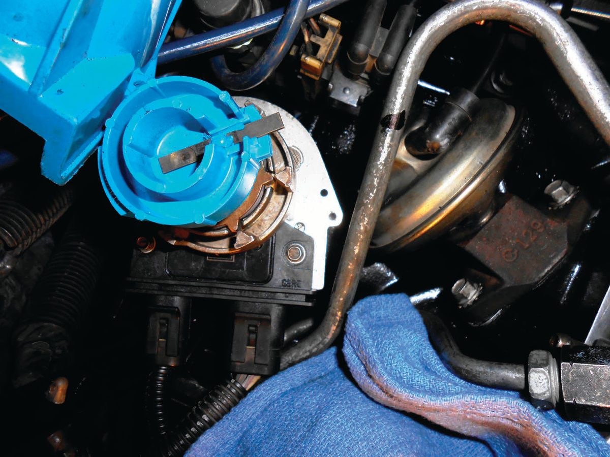
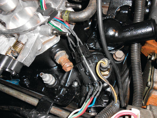
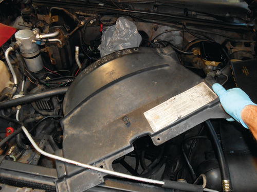
On this vehicle, the steel fuel lines are useful references in determining both. The reference mark that was made on the steel fuel line is where the rotor was pointing before removal, and should be pointing again once fully installed. And as to the distributor housing, its original position had a 1/8” gap from the fuel line, not allowing much additional counterclockwise rotation of the housing. Photo 70 shows the distributor installed, and more specifically the rotor’s orientation with relationship to the fuel line. As the distributor was lowered into the manifold opening and the gears started to mesh, the distributor shaft rotated clockwise. During installation this needs to be taken into consideration so that as it rotates it will end up pointing at the reference mark when fully installed. Had the distributor rotor ended up off target, the distributor would have been raised to the point where the gears disengaged and then the shaft rotated slightly by hand in the needed direction and another attempt made. It may take several tries; usually you are just off by one tooth.

There is one remaining thing to deal with, engaging the distributor with the drive rod for the oil pump. Notice in Photo 71 that the distributor housing isn’t completely seated on the round base gasket. It may be hard to tell, but that slight shadow on the base gasket created by the flash photo is confirmation that a gap exists. That’s because the drive tang in the bottom of the distributor gear hasn’t engaged with the slot in the drive rod; it’s riding on top of it. Spinning the engine over using the starter is one method of aligning the two. As the camshaft gear rotates the distributor gear, it will line up the drive tang with the oil pump rod and the distributor will drop in place. An option that I feel better about is to use a 15/16” socket and ½” drive ratchet and rotate the alternator pulley manually. This in turn rotates the crankshaft just as was done previously for positioning each piston. Go a little in one direction, and if it hasn’t dropped, go in the opposite direction. Occasionally push down slightly on the distributor during the manual engine rotation. In this case it dropped in at somewhere about 40° advanced. It may be perfectly safe to spin the engine over under power, but being a certified member of the “if it can go wrong it will” club, visions of broken gear teeth laying in the center of the engine come to mind; so the manual method is fine for me.
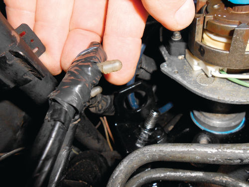
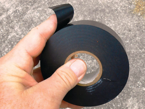
Before putting too much back together and having more obstacles to work around, a moment was taken to re-tape that loose wire mentioned in the January issue, and pictured there in Photo 17. That wire is shown in Photo 72. You may recall the plastic attaching pin had come loose from the wiring and had remained in the bracket. My point here isn’t to make a big deal about me knowing the fine art of taping wires, but about the type of tape being used. Photo 73 shows the unidentified tape that was purchased at a swap meet some time ago. It may look like ordinary electrical tape, but it has no adhesive. It’s 1.062” wide, .006” thick and shiny on both sides. If you have ever used ordinary black electrical tape under the hood of your car or most anywhere for that matter, you quickly discover its sticky residue. This wraps very easily and sticks to itself, and at the end of a run, you can use a dot of 3M Super Weather Stripping Adhesive for added insurance. Most likely the Eastwood Company carries this or something almost identical to it.

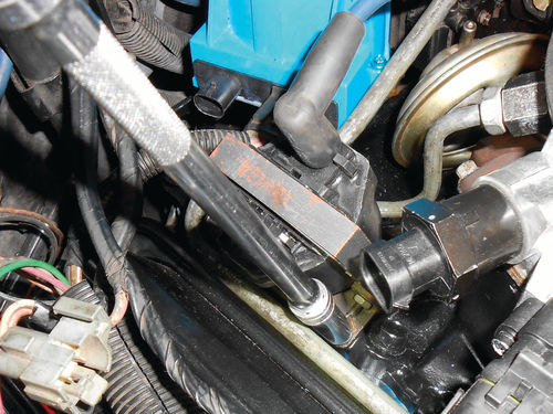
With the distributor fully seated, its retaining clamp and bolt are installed. To easily snake around obstacles and tighten the clamp, a distributor wrench is used as can be seen in Photo 74. While in the area, now is as good a time as any to replace the ignition coil. It’s secured to the manifold with two short ¼” bolts. Using a 3/8” socket on an extension is the only logical choice as seen in Photo 75.
Before you get confused looking at various photos of the TBI and thinking to yourself “something is different,” let me explain. When this Holley TBI was installed, I was unable to get weather pack connectors at my local auto parts store for making an easy injector wire disconnect, and had settled for two lead universal trailer connectors. These were bulkier, and I had left the wire too long, making it somewhat of a bunched-up mess. It worked fine, but you had to bend and tuck the extra wire to make it all fit. In the midst of ordering parts for this repair project I decided to check and see if rockauto.com had the weather pack connectors, and they did. Photo 76 shows the new connectors in place, and about 4” of wire removed from each connection, making a much neater fit.
Vacuum Hoses and Wire Routing

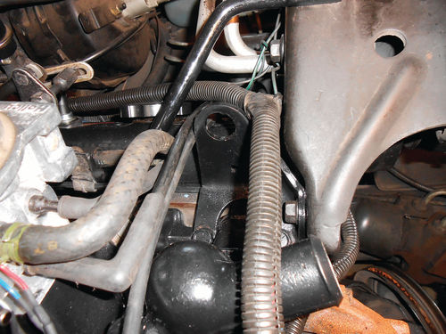
Photo 77 shows the vinyl vacuum line connected to the EGR valve and the EGR solenoid located just behind it. The other end is secured to the side of the throttle body and then connects to a junction “T.” From there one end of the “T” connects to a vacuum hose that extends over to the driver’s side wheel well where it connects to the canister purge solenoid. The other side of the “T” connects to the extreme left vacuum port on the throttle body. The way the vacuum hoses connect to this replacement Holley TBI is different than with the original Rochester TBI, so I won’t go overboard with details. Two connections that do remain the same for each TBI is the port on the rear supplies vacuum to the MAP sensor, while the largest port up front is the connection for the PVC hose. When it comes to the routing of vacuum hoses and wiring, Photo 78 shows the bulk of it comes over the left valve cover behind the A/C Compressor. As seen in the photo, the vacuum hoses are to the left of the engine lift loop, while the large plastic conduit of wiring is to the right. A smaller conduit of wire can be seen running under the A/C bracket in the front of the engine above the timing gear cover. This connects up with another larger conduit of wiring above the right valve cover. The desire is to put the wiring and vacuum hoses back in their original location. The El Camino was 10 years old when it became part of the family, so it’s possible that a previous owner might have made some under-hood changes. For the most part the hoses and wiring orientation appear correct, so all will remain in the same locations. In short, you don’t want to be embarrassed to open your hood when onlookers are standing by. Nothing will jump out quicker than wires and vacuum hoses that are obviously out of place.
So What’s Next?
The block’s casting plugs (also known as freeze plugs) are going to be replaced. That includes two up front, and two on each side of the engine. There also are two plugs located on the rear of the block but those haven’t been checked yet. If they require replacing, the transmission will need to be removed for access. So for the moment the focus will be on the six that can be accessed without disturbing the transmission, but while underneath the vehicle, we will try and view the rear casting plugs with the aid of a video scope. Also, the engine mounts will be replaced, and additionally the oil pan will be removed and cleaned, and the oil pump replaced.
The oil pan and pump weren’t part of the original list. They were added because the engine had so much sludge in it. The engine will be elevated to remove the engine mounts anyway, so the only real additional effort other than removing the oil pan and oil pump will be to remove the exhaust crossover pipe. So let’s get started.
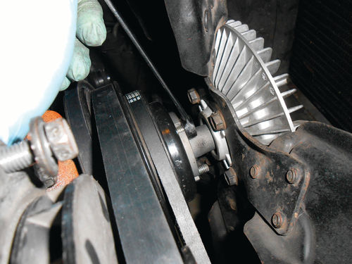
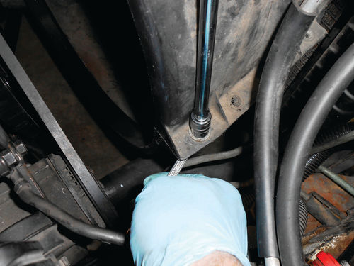

With the vehicle still sitting on the ground, now is a good time to clean off the front of the engine to gain access to the two front casting plugs. This is essentially the same procedure as replacing the water pump. Start by removing the fan using a ½” wrench as shown in Photo 79. The belts were loose, but squeezing the alternator belt between my fingers and palm gave enough resistance to keep the pulley from rotating. If necessary, a giant-size pair of slip joint pliers is another option to hold the pulley just behind where the fan bolts on. The downside is that it will certainly leave marks in the paint. Photo 80 shows that separating the top section of the fan shroud is next. It’s secured with two bolts on each side. There are four bolts that secure the leading edge of the shroud to the radiator support, and a 10mm socket and extension works well for removing them as seen in Photo 81.
Release the plastic retaining clip that holds the high-pressure aluminum A/C line connected to the top of the shroud and it’s ready to be removed. There is a lot of wiggling required to free the top of the shroud from the radiator tanks, as well as clear some of the obstacles. There’s enough flex that it can be twisted and rotated up and over the A/C Compressor as shown in Photo 82 and then removed. For additional room to move the shroud, the alternator could have been removed first. The choice is yours.

Once the top of the fan shroud has been removed, take an old section of cardboard and place it in front of the radiator as seen in Photo 83. This section is 20” square, and is cheap insurance for your radiator. The work area seems like it’s miles away from the radiator, and no one ever thinks they will accidentally damage their radiator, yet it happens.
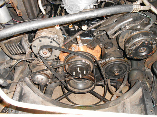
Photo 84 shows there are some obstacles to be removed before the casting plugs are accessible, however the water pump can remain. In the August through December 2014 issues of AR I did an article called “Diagnose & Replace a Faulty Water pump.” It covered the procedure of removing these components step-by-step on our 1986 Caprice. Though it has a 5L “H” code engine, the front end of the 4.3L in this article is identical. For that reason I have chosen to jump ahead a bit without referring to every nut and bolt by name. This is very straightforward; just remember to keep track of the bolts and where they came from. In most cases the bolts can be threaded back in place once an accessory has been removed.

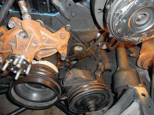

Start by removing the alternator. The top bracket had previously been removed when removing the intake, so just disconnect the wiring and thread out the large pivot bolt as seen in Photo 85. Next remove the AIR pump below it. Paying attention to the orientation of the support bar that extends from the bottom of the AIR pump to the mounting plate will save you time later. Now go over to the other side and unbolt the power steering pump from the block, leaving its hoses connected. Once loose, it can rest next to the harmonic balancer without putting any stress on the hoses as seen in Photo 86. Note in the photo there is a rear bracket for the pump that blocks the lower portion of that casting plug. Remove the one forward facing bolt in the photo, and then there a couple of studs extending from the first two exhaust manifold bolts. Loosen those nuts also. If the A/C Compressor bolts are all tightened, they will probably need to be loosened. Once the front bolt was removed and all else loosened, the bracket slid out of the way on its own. Photo 87 shows there is now clear access to the casting plug. The water pump was replaced not too long ago, and while it doesn’t need to be removed for the task at hand, it will be removed to wire brush off the rust, and paint it completely. The engine is covered in oil and grease; no doubt it needs a good cleaning.


While Photo 88 shows that the plug is much more accessible with the water pump removed, additionally removing the AIR pump’s lower bracket opens things up even more as seen in Photo 89. The bracket poses no issues for replacing the front casting plugs, but removing it allows it to be placed in the parts washer, and will make cleaning the engine and frame underneath it easier. The sides of the block are just as much of a mess as the front. So the plan of attack is to get a few obstacles out of the way, drain the remaining coolant from the block and then wash the engine as best possible. While the engine is elevated with the engine mounts removed, the casting plugs will be replaced, and then the engine will be masked off and painted in sections. There won’t be 100% coverage of paint, certain areas just won’t be accessible, but it will be a large improvement. The oil pan will be painted separately once it has been removed for cleaning.
Next, we’ll work with casting plugs and engine mounts.


