
Tackling Several Engine Projects, Pt. 7
Replacing Exhaust manifold Studs
There is no mystery when it comes to replacing most manifold studs, only the question of can they be removed without breaking them. There are two basic approaches to this, and both were used on the El Camino.
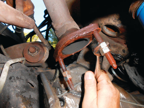
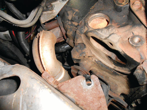
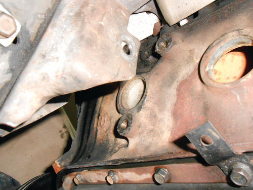
Photo 112 shows the studs on the left manifold soaked with penetrating oil. One of the studs had rotated when taking down the crossover pipe, so possibly there will be some cooperation. Two ordinary 3/8” nuts were threaded on each stud and jammed against each other, and then a wrench was used to try to back one of the studs out as seen in the photo. It moved without too much effort and then started to get tight. It was worked back and forth to help get the lubricant into the threads, and additional penetrating oil was applied. It didn’t take too much and the first stud was freed up and on its way out. The second stud was removed in the same manner. You could only wish all studs could be removed so easily.
Notice also in the photo that the flange of the manifold looks pretty rough. What you’re seeing is the remains of a gasket. A spacer fits between the manifold and pipe, and someone had used a gasket between the two mating surfaces. All references show that originally there was never a gasket used, so this requires further investigation.

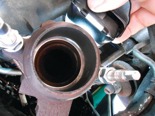
In Photo 113 the flat mating surface of the spacer has been smoothed and trued on the belt sander. In Photo 114 you are looking at the manifold flange with the studs removed and the old gasket cleaned off. Unless the exhaust manifold is removed from the engine, there is little that can be done to improve its flange surface. I would prefer to put it back together as original without a gasket, but there is a very real possibility of an exhaust leak where these surfaces mate. The thought of having to take the exhaust apart again is tiring to even think about. A simple test came to mind: Temporarily secure the spacer to the exhaust manifold with a couple of nuts and hold a light source up to the mating surfaces while watching for any light passing through.

So the threads were chased, the new studs installed and the spacer secured. Photo 115 shows the temporary test setup. Look closely and light can be seen passing between the two surfaces. If the exhaust were to be assembled as it is, there is no question there would be a leak. So what do you do when a gasket is needed, but none was ever made for a particular application? Well, I carried the spacer into NAPA and told them the application. They confirmed that nothing was shown for it, but took the spacer and disappeared into the back room to see what could be matched up.
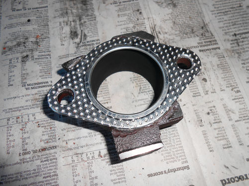
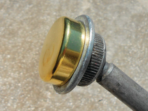
Shortly the clerk came back with a Fel-Pro #60620 catalytic converter flange gasket. In Photo 116 the gasket is placed on top of the spacer, and looks like it was made for it. This gasket fits a wide variety of vehicles, none of which happen to be GM products.
Over to the other side, the right exhaust manifold utilizes three studs, and while one was removed in the same manner as the earlier studs, the other two wouldn’t budge.
This brings us to the second stud removal method: heat. I am not referring to using a propane torch; it will never generate enough heat. I use oxy/ acetylene, although many people use propane in place of the acetylene and both will do the job.
Once again the procedure will be performed while lying on the ground. It would be much more comfortable with the vehicle on a lift, but that’s not an option, at least not yet.
A very small #0 welding tip was used to apply heat, with minimal regulator pressure. The Victor company suggests 3-5 psi for both oxygen and acetylene when using this tip. I prefer not to be waving around a long flame under the vehicle, especially around the engine, and when lying down. While it takes a little longer to heat, there is more control over the flame, and less worry of it accidentally reaching other areas and causing damage.
Of the remaining two studs, the one farthest to the right was tackled first. The torch was moved around the base of the stud, focusing the heating on the manifold until it started to glow. The torch was turned off, and immediately I attempted to remove the stud. It freed, turning a little and then it stopped. This is common, and if the threads are worked back and forth often it will release and come out. No such luck with this one, so the torch was lit again and more heat was applied. This time it was to a bright red/orange glow, and the stud put up no resistance. You certainly don’t want to force it; the heat will eventually win the battle.
The remaining stud was removed the same way, but due to the residual heat from the other stud removal, it came out much easier. The manifold was allowed to cool completely, and then the threads were chased before installing the new studs. In Photo 117 it’s easy to spot the studs that required the heat.

Take a look at Photo 118 where a new stud is placed next to one of the old ones. Notice how years, heat cycles, and the elements themselves have actually eroded the thickness of the stud and weakened the threads. Now the engine has five new healthy exhaust manifold studs, and there won’t be any concern when tightening the exhaust flanges.
Removing the Engine Mounts
Next up are the engine mounts. The through bolts have already been removed, so there are just three bolts holding each mount to the engine. The right mount has an additional bracket to secure the starter wiring as you can see in Photo 119. A 10mm wrench will remove that. The mount retaining bolts all require a 9/16” wrench.
Look again at Photo 119 and also Photo 120. On both sides of the mount there is a bunch of rubber pushing out in all directions; this made access to those top two bolts more difficult. Initially a swivel socket on an extension was tried, but a combination of long open end and deep offset box wrenches was the best option to loosen these bolts. My approach is to loosen, but not completely remove any bolts that are accessible before lifting the engine. Occasionally when an engine is elevated, the access angle to the bolts may change, and not in your favor. Also, other obstacles can seemingly come from nowhere and get in the way. In this situation, all the bolts were reached and loosened.
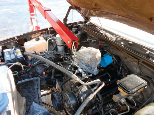
Photo 121 shows using a hoist slid in from the side with a chain connected to the front of the engine. If you look closely at the image you can see that one end of the chain is looped through the engine lift loop while the other end is secured using a longer bolt to pass through it and the intake manifold. That blue object at the rear of the engine in Photo 121 is the distributor cap that was removed to avoid breakage. A second option if you don’t have a hoist is to lift the engine from below with the help of a block of wood between the oil pan and a jack. If you go this route, be aware that as the engine is lifted, the angle of the oil pan will change the more it’s elevated, so pay close attention to the jack beneath it.
Regardless of how you lift the engine, support it as soon as possible with wood blocks (or something else that’s suitable) before placing your hands or any other body part in harm’s way.

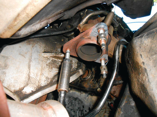
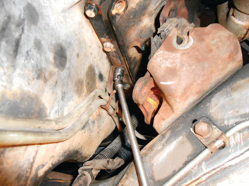
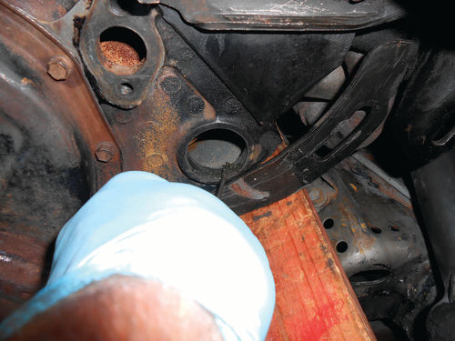
With the engine raised, the left mount was completely unbolted and slid down and out between the block and frame bracket. When attempting to do the same with the right mount, it wouldn’t fit as seen in Photo 122. The bracket that attached the transmission cooler lines to the oil pan appeared to be in the way. It will need to be loosened anyway, so in Photo 123 a 1⁄4” drive, 3/8” swivel socket is being used to unbolt it. Even with this out of the way, there still wasn’t enough room for the mount to be removed coming downward. I checked to make sure there was as much lift as possible on the engine, and there was. Removal of the large frame mounting bracket was an option if needed. Unfortunately, the nuts inside the frame weren’t welded in place, so it’s not like that would be super easy.
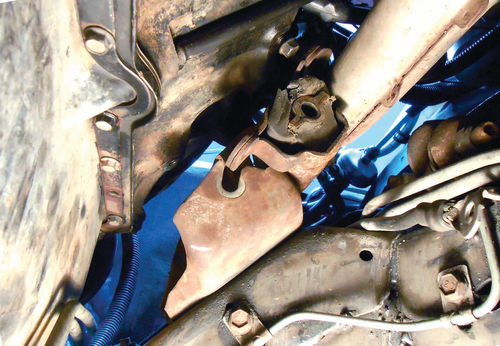
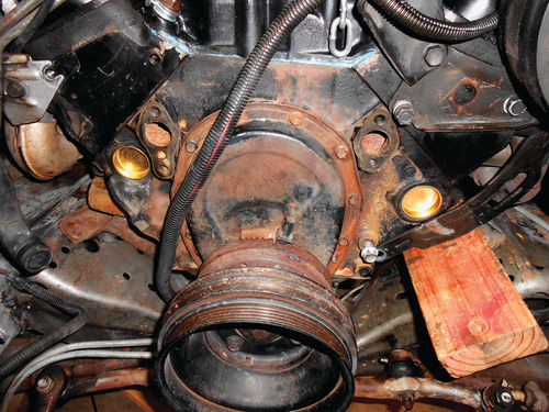
A change of direction was the answer. By raising the engine mount up until it was against the bottom of the exhaust manifold, it could be slid over the frame bracket and out toward the rear as seen in Photo 124. With the mounts removed, there was a clear view of those last two casting plugs. The left side is seen in Photo 125. They both looked fine, and as previously mentioned, the other plugs that were removed were solid and rust-free on the inside. To replace these two plugs it’s very possible that both of the frame mounting brackets would need to be removed for working space. While the cross member wouldn’t allow straight-on access, a special casting plug installation tool would do the job. But in an effort to keep this job from defining my life, the decision was made to leave those two plugs and move forward with the remainder of the project. There is no reason to expect these two plugs to ever be an issue, as long as the cooling system is properly maintained. The outside of the block still needs to be washed in the area behind the engine mounts, and then a couple of other spots will be touched up. Once that’s done, two short sections of 2x4 will be placed between the block and engine mount frame brackets. The wood blocks should allow enough room to remove the oil pan while supporting the engine. Until then, the engine remains supported by the hoist, and there is a safety support underneath the harmonic balancer.
Installing the Casting Plugs
Photo 126 shows the tools that will be used for the actual plug installation. Starting from the right, a seal driver with interchangeable ends, a casting plug installation tool with a swivel joint and interchangeable driver ends, a 1 1/8” deep socket, and a soft-faced copper hammer. Where there is easy straight-on access, for example the two front casting plugs, the seal driver and socket will be used. The special casting plug tool will take over in the harder- to-reach, offset areas.

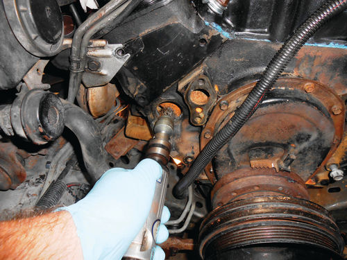
Before installing the plugs, there is some preparation. An air-powered wire wheel was briefly used to clean the casting holes as shown in Photo 127. As long as there is enough room, an electric drill would work just as well. Fine emery cloth is another option; you just want to make sure the hole is free of any residue.

Next, Photo 128 shows the application of #2 non-hardening Permatex to the casting hole with a small screwdriver. The new plug’s perimeter edge is also coated. The deep socket is used to get the plug started with a tap or two from the hammer, and then the seal driver takes over to finish the task as you see in Photo 129. Make sure the plug appears to be going in fairly straight, and once the plug’s edges are flush with the block, it’s done. The same procedure is repeated with the other front plug, and as shown in Photo 130 the front end is done.
The procedure is the same for the side casting plugs; just the access is a little less favorable. The deep socket was used to start the plug on the left side, but for the one located behind the starter a standard length socket gave me more room to tap it with the hammer. To drive in these two plugs the special casting plug installation tool was used. As seen in Photo 131, the plug sits over a boss on the adapter, and is driven in by its perimeter edge. This old Snap-on tool includes five different diameter adapters, while the ball joint at the end helps to work around obstacles. Photo 132 shows it seating the left-side casting plug. Its long extension allows it to be positioned away from things like exhaust manifolds and lower control arms, making it easy to strike with the hammer.

Time for Some Masking and Painting
Now it’s time to get some fresh paint on the block. This isn’t easy with the horses still in the corral, at least not when trying to be neat.
The engine is pretty clean, but there are still a couple of spots that need extra attention. The oil pan will be cleaned inside and out once removed, and painted off of the engine, so the focus is on the front and sides of the block. The exhaust manifold flanges will be covered with a couple of plastic bags, while newspaper and masking tape will protect the other areas. Show quality, of course not, but will I admit to doing the paint job? I should hope so.
Next, we’ll remove the oil pan and pump and install the engine mounts.


