
Tackling Several Engine Projects
As We Move Toward Wrapping Up Our Engine Work, We’ll Be Installing Some Accessories, Belts and Hoses.
Editor’s note: The author has been performing a series of repairs on the 4.3-liter V-6 engine in his 1987 El Camino. Last month he worked with the starter and used a video scope to check out the rear casting plugs. We’ve had 171 images so far and will begin here with Photo 172.
Replacing Accessories and Belts
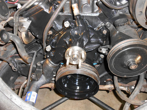
The lower power steering pump bracket that had been loosened to gain access to the left front casting plug was repositioned and securely tightened. On the opposite side the AIR pump bracket was also replaced. From here on the procedure is just like replacing the water pump. The water pump is bolted on, and the power steering pump loosely attached. Now is the easiest time to replace the lower radiator hose, and some soapy water makes it slide on more easily. Pay attention to the top hose clamp orientation. Position it where it should be accessible once the AIR pump bracket is in place, and tighten it. Also tighten the opposite clamp at the radiator. Photo 172 shows how things are starting to shape up.
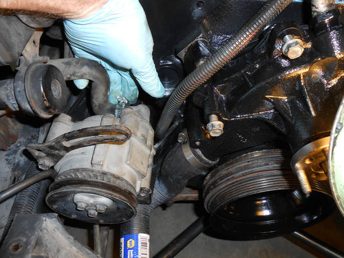
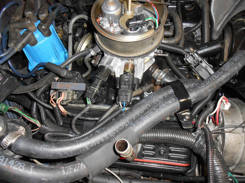
Next place the AIR pump into its bracket, and reconnect the hose connection on the back as seen in Photo 173. Secure the mounting plate to the face of the water pump with the standard bolt up top, and the bolt with stud extension below as seen in Photo 174. You can see that the AIR pump slide adjustment uses the lowest outer hole. Directly above that is the ground cable connection, and at the top is the location of the lower pivot bolt for the alternator. The pivot bolt and support bar are slid into the lower AIR pump mounting hole. At the same time the other end of that support bar will be connected to that stud as seen in Photo 175. Go back and look at that hose clamp to make certain it’s still reachable.
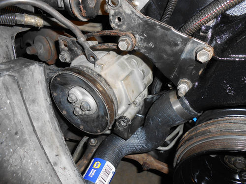

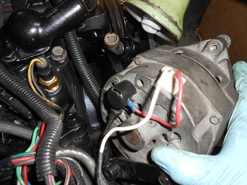
Once all is in place, the pivot bolt can be run in loosely as shown in Photo 176, and the nut securely tightened on the stud. Make sure the wiring is routed properly up behind the AIR pump, and make your connections to the alternator as seen in Photo 177.
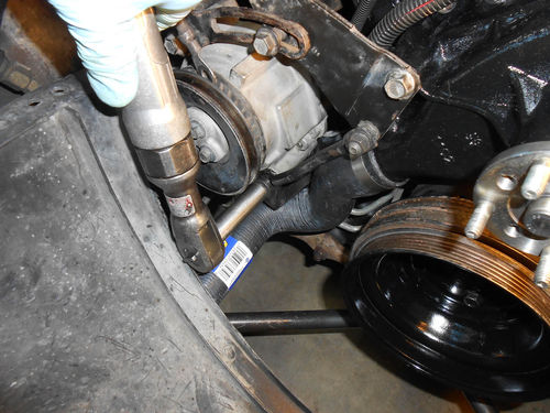
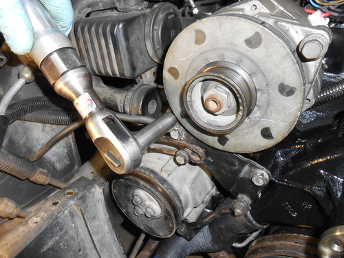
With some wiggling the alternator is lined up with the bracket and the pivot bolt cautiously started with the air ratchet as is being done in Photo 178. Should it bind, back it out and try again. In most cases it will either spin freely, or start threading in. Replace the alternator’s top mounting bracket. It bolts to the face of the water pump, top of the intake manifold, and the slide adjustment of the alternator.
Before replacing the belts, the shroud and then the fan are usually in place first. But in this instance the fan pulley is mounted and secured with a couple of nuts, leaving the fan blade and shroud off for now. This will allow a better view for photography.
The power steering is the first belt on. In Photo 179 a 5/8” eight-point socket is being used on a small ½” drive ratchet to pull up the slack on the belt, while the bolt that threads into the bracket is being tightened. This is actually a 5/8” square nut that’s welded to the bracket. If you don’t have an eight-point socket, an open end wrench will also work in most cases. Then finish tightening the remaining three fasteners. The A/C belt goes on next, followed by the alternator and then the AIR pump belts. Both the AIR pump and A/C Compressor belt adjustment is taken up with a ½” square drive ratchet that fits into each bracket. There are four fasteners for the A/C, including the pivot bolt, and just two for the AIR pump. There is an opening in the top of the alternator bracket to allow the use of a small pry bar. Apply pressure only against the forward most area of the alternator body. If you accidentally leverage against the rear of the alternator housing, closer to the engine, it will most likely crack the housing.
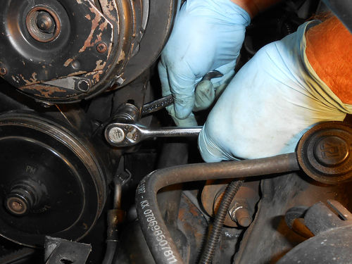
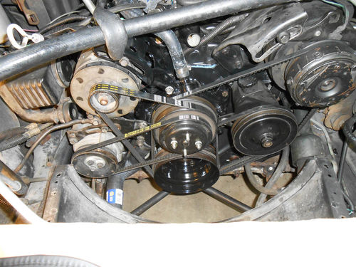
Photo 180 shows all the belts on and tightened and the large heater hose connected to the water pump. Make sure to go back over and recheck all the accessory mounting and pivot bolts for tightness. With these front engine photographs out of the way, the top of the fan shroud will be replaced and secured, followed by the fan blade, thermostat and upper radiator hose. At the beginning of this article the thought was to run a cooling system flush prior to adding fresh antifreeze, and the thermostat had been left out just for that reason. But rinsing the rust and build-up out of block did more than a chemical flush ever could, so for that reason the thermostat was replaced and the chemical flush will be skipped.
Heater Hoses
These heater hoses are preformed for this application. Both have a bend at the ends connecting to the engine, and from there on it’s straight hose, of which they give you more than enough. In Photo 181 the large ¾” hose has been marked and is ready to cut to length. On this vehicle the lengths are cut pretty close to exact, due to a lack of space. Maybe leave an extra inch, but that’s about it. On the smaller 5/8” hose a short section is cut for the space between the heater core and heater control valve as shown in Photo 182. In Photo 183 the heater hoses bend out of the way to clear the Holley TPS (throttle position sensor). On the original Rochester TBI, its TPS has the wiring connector straight up. Also notice in the photo the clamp securing both heater hoses has been rotated at an angle. Normally it’s perpendicular to the valve cover, but due to the Holley the hoses would not fit unless it was repositioned. Finally, Photo 184 shows all the hoses in place, and the reassembly is complete.


Adding Fluids & Checking the Timing
The engine is still dry, so it will need fresh coolant and oil. On any vehicle where the oil filter is mounted vertically, I prefer to fill it with oil prior to spinning it on, especially in a situation where a new oil pump has been installed. If you look back at some of the photos, you might notice an oil filter had been replaced on the engine. It was installed dry during the washing and painting for obvious reasons, but it’s been removed and filled with oil. The crankcase is then filled, followed by the cooling system.
Fill and maintain the radiator level to about 8” down inside the tank. There is quite a bit of air trapped inside the cooling system, so if the radiator is filled to the top, antifreeze will end up on your floor as the engine warms up. Start the engine and remember to turn on the vehicle’s heater while filling the system. When movement is visible inside the radiator tank, that indicates the thermostat has opened, the radiator can be filled and its cap replaced. Then bring the overflow tank up to the proper level. Dye will be added to the engine, with the primary concern being to check for leaks on the back of the engine behind the flex plate. The question is which system to leak test first? Antifreeze has a distinct sweet smell, making it possibly easier to spot with a simple pressure test. For the moment a regular visual check is made under the vehicle for any obvious leaks. The dye can be added at any time.
The other system of concern when it comes to leaks is the exhaust. Remember the exhaust manifold flange where the gasket was added? Well it and the rest of the exhaust system sealed up perfectly.
Next it’s on to setting the ignition timing. The Electronic Spark Timing (EST) must be disabled before adjusting the base timing. This prevents the computer from adding or subtracting ignition timing. On the El Camino there is a beige wire with a black stripe located on the right fender well in front of the A/C accumulator that must be unplugged for this purpose.


