Tackling Several Engine Projects, Pt. 7
Oil Pan and Pump Removal
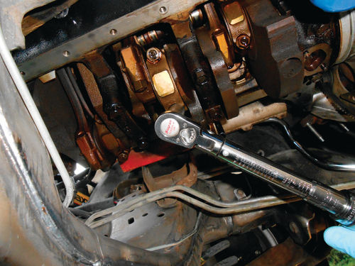
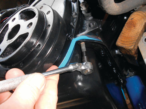
The pan is poised and ready to come off. Everything is out of the way, and a 1⁄4” drive, 3/8” swivel socket is used to remove most of the fasteners as seen in Photo 133. The smaller 1⁄4” drive is less bulky, and can deliver all the torque that’s needed to remove these small bolts. There are two studs located on each end of the oil pan, and a 1⁄2” drive deep socket will replace the swivel socket for removing those.
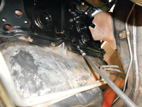

Once all have been removed, the oil pan reinforcement rails come down first followed by the oil pan as seen in Photo 134. The pan is tipped down in the rear to clear the flex plate and torque converter. It’s a close fit, but it will come out. Remember to have the harmonic balancer positioned with the timing mark at 6 o’clock. This will put the crankshaft’s forward counterweights up inside the block giving the clearance needed to slide out the oil pan.
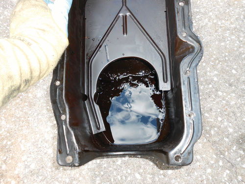
Photo 135 looks inside the removed oil pan. There was some sludge, but not as much as was expected. Also there were some chunks of fiber, most likely from a factory timing gear that had let go at some point in history before the vehicle joined our family.
Speaking of timing gears, many readers might be wondering why in the world the timing cover hasn’t been removed to get a look at the chain and gears. That’s a valid question, and something that should be done. After all, with the oil pan off, there’s no easier time to replace the chain and gear set. But the reason I’m not doing that is simple; they were all replaced very recently. I had a wakeup call when the nylon teeth sheared off the original factory gear in our 1986 Caprice, so preventative maintenance was performed with the El Camino and all was replaced.
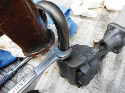
With that explained, the oil pan is set aside to be cleaned and painted before reinstallation. The oil pump is now in plain view, and a 5/8” socket, extension and 1⁄2” drive breaker bar (flex handle to some folks) are the tools of choice for removal as seen in Photo 136.
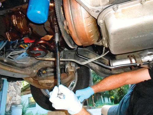
Once the bolt is removed, the base of the pump requires several taps with a hammer to free it. Lower it straight down until the oil pump’s drive rod clears the engine, and set it aside. A new pump will be going back in its place, but the pickup screen will be removed from the old pump, cleaned and installed on the new pump. There is some masking and painting that still needs to be done, and having the oil pan off yields a little extra room. Replacing the pump at this time would just make masking the bottom end of the engine a bit more difficult, so for the moment that will wait.
At this point it’s never a bad idea to take a look at a connecting rod bearing or two. If there are any issues, it makes sense to discover them now, and think out the options. The #4 connecting rod was currently a low throw on the crankshaft and conveniently located, so its cap was unbolted. To remove it requires some gentle tapping back and forth on each side to free the bond. Carefully work it off the connecting rod studs. With the cap removed, there is a clear view of the lower half of the bearing insert as seen in Photo 137. Sure there is some visible wear on the insert, but nothing that has me running to the parts store. The engine has 225,000 miles on it, so that isn’t surprising, and the crankshaft journal looks fine. That perpendicular line going across the bottom of the insert is a small section of Plastigauge. If you’re not familiar with the product, it’s an inexpensive and accurate method used to measure bearing clearance. It is available in a couple of sizes, so you should know ahead of time the clearance range that’s required for your project. However, most good parts clerks will likely know what you need.

For this engine the connecting rod clearance range is .0013”-.0035”. Remove the insert wiping both it and the bearing cap dry, and then replace the insert in the bearing cap. Also wipe the crankshaft journal dry as well. Place the Plastigauge across the bearing as shown in Photo 137, and carefully slide it onto the connecting rod studs. Progressively torque each stud until the desired torque level has been reached, (in this case 45 foot pounds) as shown in Photo 138. Then loosen the nuts and carefully remove the cap. The crushed Plastigauge is then measured against the paper sleeve that it came in to indicate the clearance as is being done in Photo 139.
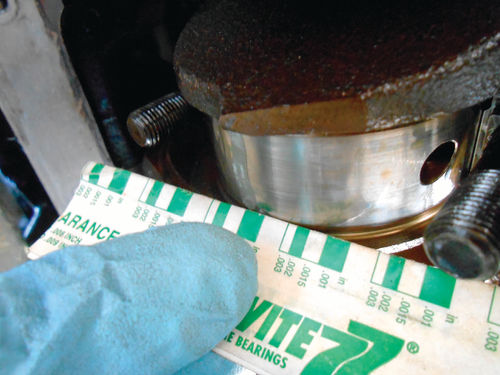
If the width of the compressed Plastigauge is larger at one side than the other, this usually indicates a tapered journal. This journal is showing a clearance of .0015”. To possibly be a bit more accurate, the top insert could also be removed, and the entire journal and insert wiped free of oil for the test. Had this been a vehicle of unknown history, considerably more time would be spent checking the bearings and crankshaft journals. For more information about Plastigauge and how to use it, visit www.plastigaugeusa.com.
Installing the Oil pump and Pan
Before bolting on the new oil pump there are a few things to do. First remove the drive rod from the pump if it hasn’t already come loose. The plastic/nylon collar that joins the rod to the pump will be brittle with age, so usually a little sideways wobble is all that’s needed to pop the joining collar in half, and free the rod. Another collar is included with the new pump, but don’t install it just yet. The new pump doesn’t include a pickup screen; you either have to reuse the old one or purchase a new one. This one is perfectly serviceable, only needing to be cleaned. To remove it, secure the old pump in a vise, and while grabbing the pickup with your hands, rotate it back and forth while pulling it away from the pump.
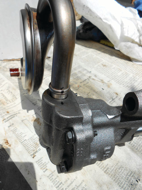
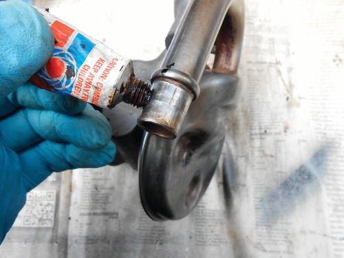
Once free, clean and dry the pickup screen thoroughly. As a general rule, the pickup screen is perpendicular to the pump body. One manual stated the pickup should be installed parallel with the oil pan mounting rails on the block. To do this, the pump can be either held in place by hand, or loosely secured to the block with its bolt. Temporarily install the pickup with no more than hand pressure, there will be enough friction to keep the screen in place when you move it. Now judge it in relationship to the oil pan mounting rails, and move the pickup accordingly. When satisfied that it’s parallel, make a mark on the pump and tube with a sharpie so that you can reassemble it in the same location. Photo 140 shows the reference mark. Next remove and coat the inlet of the tube with a sealer; Permatex #1 is being used in Photo 141. Insert the tube into the pump with the marks aligned. The best method to install the pickup tube is to rest a snug- fitting open end wrench on the raised edge and tap it in with a hammer until it’s completely seated as seen in Photo 142. Clean up the drive rod and insert the plastic/nylon coupler onto the end as shown in Photo 143. If you prefer, it could be installed on the pump instead, it makes no difference. Line up the drive tang on the rod with the pump and slide the two together until you hear it snap in place. Photo 144 shows the drive rod installed and almost ready to be replaced in the engine.


The final task is to prime the pump. Start with a clean container that is large enough for the pickup screen to fit down into, and add enough clean oil so that the screen is covered. The distributor rotates clockwise in this vehicle, which means the oil pump will also. As you are looking down at the top of the pump, rotate the drive rod clockwise until oil starts pumping out of its discharge port. Now the pump can be installed in the engine. Carefully insert the drive rod up into the block. Odds are it won’t line up with the distributor at first. So if the pump will not sit flat, rotate the drive rod with your fingertips a little at a time until it finally does rest completely flat on the rear main bearing cap. Now the retaining bolt is replaced to a torque of 60 foot pounds.
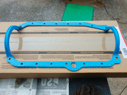
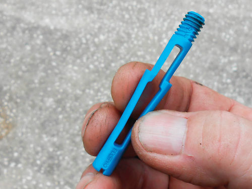
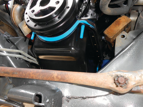
With the oil pan cleaned and painted, and all the mounting surfaces free of any residue, it’s time to install the new gasket. Photo 145 shows the substantial one-piece gasket made by Fel-Pro. This is to be installed completely dry, using no adhesives. Additionally, Fel-Pro included a package of what they call “snap-ups.” This was a new experience for me, but certainly a positive one. The oil pan guide studs are removed from both ends of the block, and the plastic “snap-up” guides seen in Photo 146 are threaded in their place. The shoulder below the threads will hold the gasket; followed by the oil pan and rails until the remaining bolts have been started. Photo 147 shows them in position and the new gasket held in place. I was concerned that the front snap-ups might extend down so far that the oil pan couldn’t fit under them, but it did. They have some flex in them anyway so that helps too. Had the oil pan not cleared them, they could have been momentarily removed; the pan slid into position over the cross member, and then the snap-ups threaded back in. Photo 148 shows the oil pan now being suspended by these four plastic guides. The reinforcement rails are stacked on next, and then the bolts are all loosely threaded in place. The snap- ups can then be removed and a Torx socket used to reinstall the studs as is being done in Photo 149. These guides were easy enough to thread in and out by hand, but if tight, or in a difficult location, there is a slot in the bottom of each so a straight-blade screwdriver can be used for removal. The torque specifications are 10 foot-pounds for the bolts, and 30 foot-pounds for the four nuts at the corners. These snap- up guides were a huge time saver, and made the installation a breeze.

Replacing the Engine Mounts
In Photo 150 the two mounts in the center are the old ones; to the far right is the new left mount, while on the opposite end is the new right mount. Curiously, while these new mounts were boxed, the right mount had a paper tag stuck to it with a handwritten part number. That would come back to haunt me later.
Aside from differences in their metal frames, they all look quite similar. That wouldn’t seem unusual as they likely represent three different manufacturers. That old right mount is believed to be original equipment, and the left one replaced at some point. Prior to installation no other differences were spotted. While the NAPA receipt shows each part number, it doesn’t tell you which is the left or right application. To avoid any confusion a phone call was made to NAPA and each box was then marked.

You would think bolting the mounts on would be nothing short of simple, or at least it should be. The left engine mount was the first to go on, the first two bolts would line up fine, but the third wouldn’t. Even when trying different bolt combinations the outcome was the same; two yes, three, no.
The engine hoist was used to obtain a little extra lift, thinking that the mount was catching on something inside the frame mounting bracket. Still there was no luck. A closer look showed that the mount was laying flat against the three mounting bosses on the block, and a small mirror confirmed that the third hole simply wasn’t quite lining up. These three mounting bosses have remained unchanged since side engine mounts were introduced many decades ago on early small block engines. The new mount was removed to find out what the problem was. Think of these mounts like a sandwich; a metal base; rubber inside; and another piece of metal wrapping around that joins up with the base plate. Both pieces of metal are machined with the mounting holes, but they were very slightly misaligned.
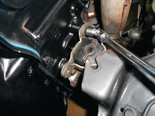
A few passes with a round file was all it took to correct the problem, and then it bolted to the block without any problem. A closer visual inspection was made of the right engine mount, and its mounting holes looked good. Photo 151 shows it being secured to the block with the swivel socket; the tool that couldn’t be used to remove the old mount due to all the loose rubber hanging out.

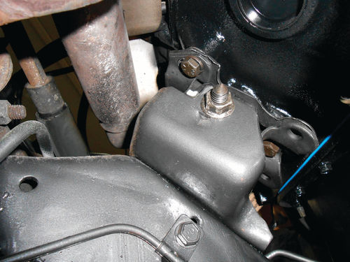
Next some pressure was released from the hoist allowing the engine to lower and get the left mount close, but it still needed some alignment help as seen in Photo 152. This was followed by using an air ratchet to feed the bolt in under power as seen in Photo 153. Instead of trying to push it in by hand and fighting with the rubber grabbing onto the bolt, the right-hand threads and clockwise rotation of the bolt were used to pull itself in. Photo 154 shows the mount from the rear once the nut was in place, but not fully tightened. Take a close look at the photo and you will notice above and to the left of the nut there is a white spot. This is actually a metal ear that’s part of the engine mount, and rests on the frame mount when fully installed. The dot of white paint was added to aid in visibility. Before completely tightening the through bolt on this mount, let’s move over to the right mount and get it lined up. It didn’t take long to realize those metal ears that rested so nicely on the left engine frame mounting bracket were preventing the right engine mount from settling into its frame mount. Photo 155 shows the front view of the mount. See the metal ear at about 10 o’clock with relation to the bolt hole. If you look again at Photo 151 the ear on the back side is located just below the socket. There is no way this mount was going to fit into the frame bracket. It was difficult to do much of a comparison by looking at the old blown-out mount, but no ears were visible.

A visit to www.rockauto.com and a look at some images of engine mounts showed the left mount with these ears, but not the right. It seems that I ended up with two left engine mounts. Most likely someone purchased a couple of mounts and for whatever reason returned them in the wrong boxes, and one of them landed with me.
So what’s next? To go into town means getting cleaned up to at least appear human, and that’s a 25-mile round trip to the parts store. Naturally there was no guarantee that one would be in stock; a phone call would need to be made and, most importantly, I would need to look at the mount myself. Sure, that’s the right thing to do, return it and get the correct mount. But even if one was in stock, this would pretty much blow a big hole in the day.
So, now that I was feeling like an authority on these engine mounts, and no other differences were spotted, the decision was made to cut off the ears. I am not recommending doing this, but it was the best option at the time. Certainly if there is any warranty offered by NAPA, it was just voided. The mount was then re-bolted to the block and manipulated until it was lined up with its frame mount, and secured with the through bolt. Naturally it wasn’t quick and easy. There was some up and down with the hoist trying to line it up with the frame mounting bracket, but eventually the bolt went in. Once tight, a return visit was made to the other mount to finish tightening it.
There are a few small tasks like installing the knock sensor and securing its wire stand off to an oil pan bolt. That threaded (drain) hole where the sensor will be installed had a steel plug in it during the painting. On the other side there is a transmission line clip that secures to the pan below the engine mount. Finally, the wiring for the starter has a bracket that bolts to the front lower corner of the engine mount, but the bolt won’t fit. After wasting time fiddling with it, a comparison of the two old mounts was made in Photo 156. The hole circled in white is where the bolt had been previously. Compare it to the old left mount and you see the problem. So there is still one more hurdle to overcome with this mount. The only thing certain at this point was that the mounts were not coming off.

This area is positioned directly above the cross member so access is poor, and the options are few. I started with a small file, making the shortest strokes back and forth. This felt like an attempt to break out of prison. That approach was short-lived. Maybe discard the original bolt and threaded clip, and install a smaller bolt and nut? This sounded good, and while it wouldn’t be “as original,” it would do the job. The tight working space though made it impossible to get my fingers where they needed to be and successfully thread the nut on once all was in place.
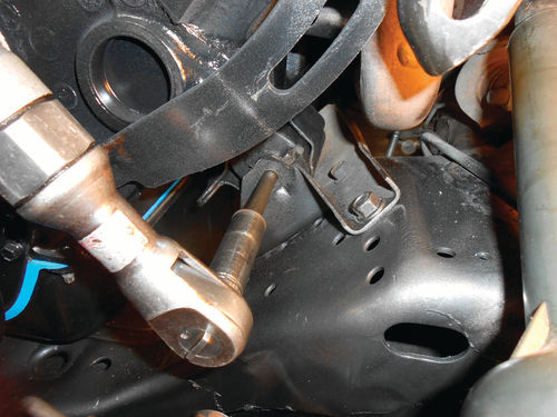
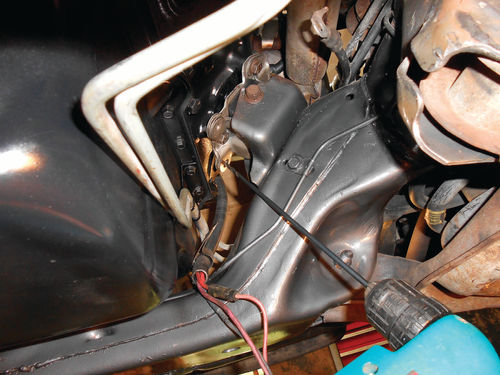
The next thought was to enlarge the hole using a long drill bit going in at an angle as shown in Photo 157. The odds of breaking this long bit were pretty good, but options were running out so it was worth a try. Approaching at an angle like this is certainly risky, and my eye protection was on in the event the bit jammed and broke. A very light drilling approach was taken, and the bit successfully made it through the hole. Carefully it was wobbled around in an attempt to open it up a little more, again with the very real possibility of losing a drill bit in the process.
The bit survived, and the original bolt once again fit where it was supposed to go. Next, we’ll install the starter along with some accessories, belts and hoses.


