Replacing Fuel Injection With Carburetors
The Numerous New Parts Need to Be TestFitted to Be Certain This Project Will Work. Fortunately, an Unexpected Helper Appeared.
Editor’s note: You’ve probably noticed that we have two contributors by the name of Bauske—Carl and Brian—taking part in the magazine on a regular basis. The brothers have been involved with vintage vehicles for some time and while Carl currently is working on his Volvo 245 as recounted here, Brian is restoring his 1964 Mercedes 230SL and his latest article is on page 29.
In the first episode, I described the project steps for switching Buster, the 1986 autocross Volvo 245, from Bosch Jetronic LH 2.2 fuel injection to Weber carburetors. We’ll start here with Photo 8. For a quick review, here are the steps involved:
1. Run the car on a chassis dynamometer to establish a baseline (already completed and reported on last month).
2. Replace his intake manifold and throttle body with a manifold that interfaces with two 45DCOE Weber side-draft carburetors.
3. Modify his fuel supply system to deliver gas at 3.5 psi to the carburetors instead of 36 psi to the fuel injectors. We must also remove control over his two fuel pumps from the Bosch 2.2 ECU (electronic control unit) and rewire them for manual operation.
4. Replace his present throttle linkage with a suitable setup.
5. Replace his distributor and Chrysler ignition controller with a new programmable 123Tune distributor made by Albertronic in the Netherlands.
6. Install an electric vacuum pump to power the brake booster and HVAC control vanes.
7. Remove any remaining underhood items that are no longer required.
8. Run the car again on the same chassis dynamometer and tune the induction and ignition systems for optimum performance. Now let’s move to the next step in the process:
Step 2. Test fit the induction system.
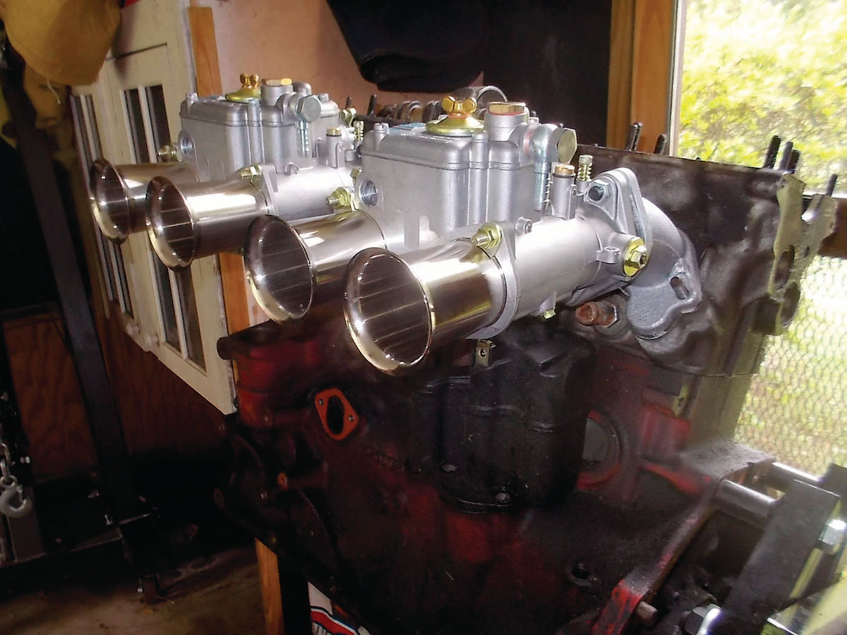
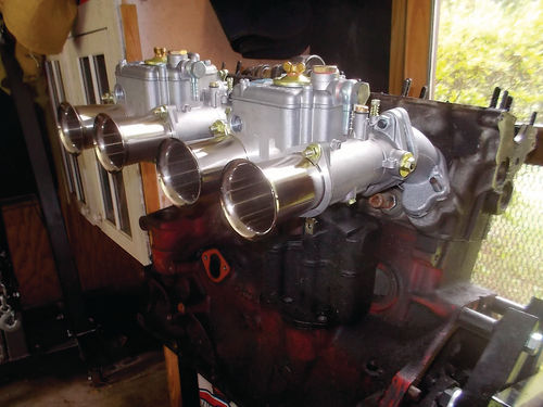
First I fit the new parts on a stripped block and head in my garage (Photo 8). This is a spare engine from a 1991 Volvo 244 that was the donor for the 5-speed manual transmission swap done several years ago. This mule engine also gave me a chance to test fit the throttle linkage. (See Step 4 below.)
Here is a video of the throttle linkage operating: https://www.youtube.com/ watch?v=z-PzIcZX2Ug
I was happy to find that the original Volvo throttle cable could be used to actuate the throttles of the 45DCOEs (Photos 9 & 10). This simplified what lay ahead and provided a smooth action, so important to drivability.


The Arrival of the Volvo Dinosaur
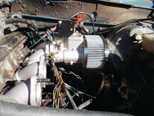
Sometimes life deals us a hand that changes our course. The surprise hand that changed this step was the arrival of Dino (the dinosaur), a blue (sort of) 1985 Volvo 244 sedan (Photo 11). Poor old Dino is rusted out, infested with mice underneath somewhere, has disconnected power steering, and a suspension that is questionable.

But three things that Dino also has are a running engine, an operating drive train and working brakes. Oh, and all his lights and signals work too. Dino was cheap ($300) and even came with free delivery right into my driveway. I think his 4-speed transmission with Laycock de Normanville overdrive alone was worth the $300.
But inside the trunk and cabin he is the dirtiest car I have seen, full of dog hair and most of the red clay dust of the Virginia Piedmont.
So here was a chance to try out the Webers without tearing into Buster. These cars are 30 years old with very complex wiring and many hoses and tubes that are also decaying. I was afraid that if the Webers did not fit or work, getting Buster back to working order again might be very difficult and expensive.
So I took the induction system off Dino’s engine. I tried not to mess things up too badly, but I knew for safety’s sake he might never drive again. But he did have a chance to prove the Webers would fit and could be tested to some degree for function. The perceived state of decay was real. Many hoses and wires crumbled in my hands. It became obvious that for a major change like this, it was not easy to go back.
Here’s another tip for others working on old cars: Count the nuts and washers before and after removing an intake manifold. It’s good to know that none of them went down an intake runner.
It was relatively straightforward to remove the induction path components. I saved the MAF and all the other usable fuel injection parts including the ECU, fuel rail with injectors, throttle body, ignition controller and any pipes and hoses that were viable.
The only tricky bit was the intake manifold itself. Volvo ran the entire engine wiring harness through a “hole” in the manifold. This hole was formed by two of the intake runners (cylinders 3 and 4) and a cast-in brace between the flanges that bolt to the cylinder head. I used a Sawzall to cut out the brace rather than attempt to thread the entire harness through the hole. I could have cut the harness but I still needed basic electrics to function, such as the ignition, the starter and the alternator connections.
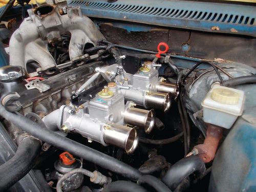
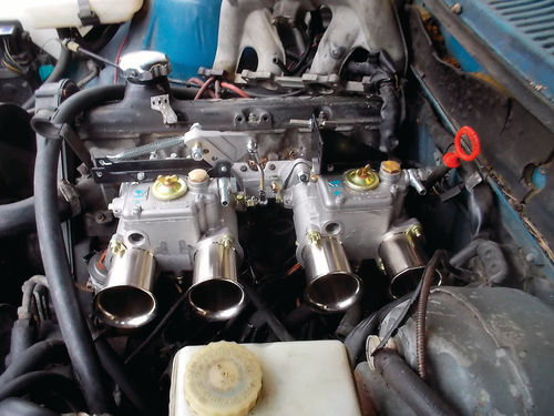
With the removal of the FI equipment, it was time to test fit the new induction. I put Vaseline on both sides of the intake manifold gasket, a hard composite pressing supplied by IPD in Portland, and bolted on the manifold complete with the two Webers. To my satisfaction they fit! This was the goal of Step 2. Would they physically fit between the cylinder head and the big vacuum brake booster? Yes, with a little room to spare (Photos 12, 13 & 14).
Step 3. Modify the Fuel System
Since we decided to go ahead and test the carburetor setup in Dino, we proceeded to Step 3, the fuel system. This was made straightforward by the abundance of after-market automotive equipment available today. We found that Aeromotive makes a 5-star-rated return-type fuel pressure regulator that is suitable for use with Weber carburetors’ required 3.5 psi fuel delivery pressure. The Aeromotive regulator, supplied by Summit Racing, has an unbelievable adjustment range of 3 psi to 65 psi, comes with its own mounting bracket, and can directly replace the Volvo regulator which is also return type. A return-type regulator returns the excess fuel supplied by the pumps back to the tank via a separate return line. This is necessary with the Volvo as the main fuel pump is cooled by the fuel flowing through it. It would overheat if used with a non-return regulator. The other pump is in the fuel tank.
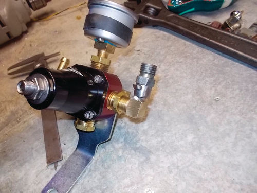
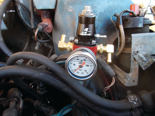
All the connections to the regulator are 3/8 inch National Pipe Thread (NPT). NAPA Auto Parts in Charlottesville supplied all the NPT fittings and hoses required. To attach the new regulator to the feed line from the pumps and filter, I cut a fitting off the old Volvo regulator and machined a brass NPT nipple to be an interference fit into this Volvo fitting that accepted attachment to the fuel supply hose, and pressed them together in my vise. To be sure it would stay in place I sweated the joint with silver solder (Photo 15). I mounted the regulator in a place where the existing feed hose would reach and the gauge would be easy to read (Photo 16).
I connected a new ISO-type relay between the battery and the fuel pumps via the existing fuse. The relay coil is operated by the ignition circuit also via an existing fuse and I adjusted the regulator for 3.5 psi. The regulator has enough outputs (three) for a pressure gauge from Auto Meter Products, and a hose fitting for each carburetor. I used Permatex High Temperature Thread Sealant #59235 on all the threaded joints. This is much better for fuel fittings than Teflon tape. I connected the two fuel hoses to the Webers and tested the system for leaks. I had no seepage at all. So that was the goal of Step 3. Now, just by turning on the ignition, we had 3.5 psi to both 45DCOEs.
Step 4. Throttle Linkage
During last year’s racing season I asked a friend in the autocross club with welding skills if he could weld an extension onto a piece of the throttle linkage that joins the two carburetor throttle shafts together. (Refer back to Photo 9.) This was necessary as the part supplied was too short. I am sure it was designed for a different application. KGTrimning had told us this would be necessary, so it was not a surprise.
I also took the time to mock-up the new induction system on a Volvo motor block and head that I have in my garage on an engine stand (Photo 10). This is a nice thing to have when you are wondering exactly where this-or-that is attached deep down along the side of an engine. I also had a piece of firewall to which the throttle pedal and throttle cable are mounted in a 240. I clamped this piece of firewall to the engine stand approximately where it is in the car (Photo 10).
Using this mock-up I checked to see if I could utilize the standard Volvo 240 throttle pedal and cable, unaltered, to connect to the linkage supplied by KGTrimning. It was easy and straightforward, requiring only a wedge-shaped ring to be cut from pipe and slipped onto the throttle cable’s attachment flange at the firewall, to angle the cable more upright to clear the new air filters.
With that, we’ve finished Step 4.
Step 5. The Ignition System
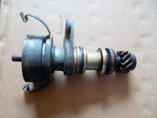
Along with all the parts to convert the induction system, KGTrimning also supplied a 123Tune programmable distributor Model ‘B21-B23’, designed specifically for the Volvo “redblock” engines like Buster’s (Photos 17 & 18). Made in the Netherlands by Albertronic, the 123Tune is a completely selfcontained ignition system with two stored advance curves, connections to the coil and ground, and a USB interface for a laptop to create and store the advance curves. You are allowed to dynamically switch between the two curves at anytime by switching the yellow wire from ground (Curve 1) to B+ (Curve 2). It also has provision for a manifold pressure input in the form of a small pipe nipple on the housing. We will not use this feature. It is primarily intended for turbocharged engines.

I downloaded the software from Albertronics onto my Windows laptop and programmed the distributor months before I installed it. It was exquisitely simple and intuitive to do.
Using a standard USB cable, the distributor is connected to the laptop. I looked up some sample centrifugal advance curves on the Internet. I made one curve (Curve 1) and was sent a curve by KGTrimning that was stored as Curve 2. These two curves would be a starting place, and they were loaded into the 123Tune before installing it in the engine. When we do testing on the Dynamometer in Step 8, we can try both. You can share curves with others who use 123Tune distributors by sending them through email as an uploaded file. The files are .xml for you computer types.
It was necessary to transfer the gear to the new distributor. It is held in place with a roll pin. To set the static timing is also as simple as can be. You turn the engine to TDC cylinder #1. Note the position of the rotor (where is it pointing?). Then pull out the old distributor and insert the 123Tune so that the rotor ends up in the same position. Then by loosening the adjustment bolt on the distributor base, rotate the distributor backward until a little green LED just illuminates. Lock the distributor down and you are done. You should check the setting with a timing light later, but this is close enough to run the engine. So far, so good. But will it run?
I could have made you wait until the next episode, but I won’t. Weber 45DCOE models have an enrichment or starting carburetor built into them. These have a small external lever that can be attached to a cable just like a choke mechanism. I rigged up a temporary connection and hit the key. The Dino car fired immediately and settled to a smooth idle. As it warmed up I let off the enrichment while I balanced the throttle linkage between the two carbs and adjusted the main throttle stop for an 800 rpm idle. I never had to touch the idle mix screws until I started changing jets (Step 8). But that will wait until a further episode. We will begin the next installment with the move of all this equipment to Buster.
Resources
Summit Racing Equipment www.summitracing.com
KGTrimning Sandby 412 Lindegård 247 34 Södra Sandby Sweden www.kgtrimning.com
IPD 11744 NE Ainsworth Circle Portland OR 97220 www.ipdusa.com
Albertronic BV 123Tune www.123ignition.nl


