
Replacing Fuel Injection With Carburetors
It’s Time to Wrap Up the Project and Run Some Tests to Measure Our Gains (or Losses) With the New Carb System.
In the first article in this series, I described the project steps for switching Buster, my autocross Volvo 245, from Bosch Jetronic LH 2.2 fuel injection to Weber carburetors. We have worked through all the steps except No. 8. The third installment ended with Photo 22, so we’ll pick up here with 23. For a quick review of the project, here are the steps and their status:
1. Run the car on a chassis dynamometer to establish a baseline (completed).
2. Replace the car’s intake manifold and throttle body with a manifold that interfaces with two 45DCOE Weber sidedraft carburetors (completed).
3. Modify his fuel supply system to deliver gas at 3.5 psi to the carburetors instead of the 36 psi required for the fuel injectors. We also must remove control over his two fuel pumps from the Bosch 2.2 ECU and rewire them for manual operation (completed).
4. Replace his present throttle linkage with a suitable setup (completed).
5. Replace his distributor and Chrysler ignition controller with a new programmable 123Tune distributor made by Albertronic in the Netherlands (completed).
6. Install an electric vacuum pump to power the brake booster and HVAC control vanes (completed).
7. Remove any remaining underhood items that are no longer required (completed).
8. Run the car on the same chassis dynamometer and tune the induction and ignition systems for optimum performance.
Finishing the Project
This episode is all about Step 8: Tuning and adjusting for maximum power.
What we needed now was a lot of skill or a good dose of technology. I searched the Internet for skill but could not find any for sale. But there is a lot of useful skillbuilding information in the book “Weber Carburetors” by Pat Braden, and using this reference alone it would be possible, but not easy, to get through the jetting.
Weber jets are not cheap, so it is impractical to buy one of every size. It would be nice to ask an expert for some skill, but our parts-supplier buddies in Sweden reminded us (nicely) that they had never tried putting these Webers on a stock motor and although they sent along some extra jets they thought would be close; they said that we were flying in new territory. They suggested we go straight for the goal by adding an Air/Fuel Ratio (AFR) meter to Buster.
These clever little devices use a broadband O2 sensor attached to a sophisticated meter to directly indicate air/fuel ratio by examining the exhaust stream in real time. And since we want to get the mix just right for a dynamometer pull, it seemed like a cool idea. Besides, who doesn’t like gauges
Let’s Get the Needed Parts
Back we go to Summit Racing for an Innovate Motorsports MTX-L Air/Fuel Ratio meter kit, part number INN-3844.
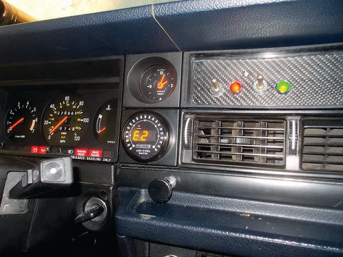
The Volvo has just the spot on the dash, made for a 2-inch gauge, that made installation a snap. Reading the instructions told us that we could not use the current O2 sensor location for the meter. It must be at least 24 inches from the nearest exhaust port in the cylinder head. The old location was about 12 inches downstream and actually screwed into the exhaust manifold. This location could overheat the Bosch broadband sensor so we needed a new location. The kit includes a weld-on O2 sensor bung that is the right length to position the end of the sensor even with the inside wall of the exhaust pipe.
Installing the Sensor
We drove Buster (about a 130-mile round trip) to visit the beautiful home garage built by Justin, another friend in our autocross club. He built this huge structure with a little help from friends.
When he needed to hoist the steel girders that support the roof, he rented a crane. He installed the HVAC, the wiring, the air lines and all the other fittings himself. It is fabulous. It’s insulated, heated and cooled, well-lit and completely equipped for any job. His current project is building a roadster kit car for his dad.
Justin put Buster on his lift and removed the headpipe. As you might expect, one of the three studs in the exhaust manifold flange broke with about 3/8-inch sticking out. By heating it and putting penetrating fluid on it, he got it out with a stud extractor tool.
Justin hammered a flat spot on the top of the headpipe where it goes past the transmission, cut a 3/4-inch hole and then wire-welded the bung on. I used nylon cable straps and self-starting sheet metal screws to keep the wires away from the exhaust and up the firewall. So when Buster came off the lift he had a working AFR meter (Photo 23). My daughter Amanda and I set the idle mix with the meter while we were still in Justin’s driveway. It was very close already. On the drive back home it was obvious that the progression circuit was lean and the main circuit was rich.
About Those Weber Jets
Weber jets are all numbered. Normally the numbers indicate the size of the hole in the jet in hundredths of a millimeter. So a #150 main jet is 1.50mm. This is fine and true up to a point. First of all you have to remember that it is not linear. The area of a hole has more to do with how much air or fuel it will pass than its diameter and the area increases with the square of the diameter.
Also, for some of the holes in Weber jets, the numbers are not related to the size. For instance, the progression jet in a 45DCOE is numbered like this: 60 F8. The 60 indicated a 0.60mm fuel drilling, but the F8 is like a family name. F8 is a standard air correction size. F9 is richer and F6 is richer still. I have no idea why or how this came about. For progression jets, the Weber book noted above advises that you try to stay in one family like F8 and just change the size of the fuel hole.
To address the rich main circuit, I went back to the book once more and applied a ROT (rule of thumb). The ROT states that you take the size of your throat (36mm) and multiply it times 4 (144) and that is the number of your main jet. I put in #145s that came in the carbs. The main circuit also depends on an air correction jet that acts as a brake to stop too much fuel at the highest speeds. This is not the speed of the car; it is the speed of air through the throat. For a starting point the book says add 60 to the main jet size (204) so I put in 200 A/C jets. This brought the main jet mixture to nearly correct. Our WOT target is around 13:1- 13.5:1 AFR. With these jets we had about 12:1. So I ordered #140 and #135. Buster has 140s in now but in the hot weather these may be too rich still.
Is There a Good Reason for Being So Intricate?
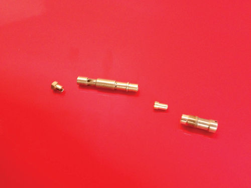
Also, the accelerator pump seemed to be a bit weak as well. I thought this because if you opened the throttles very slowly, it got lean during progression but not with such a fuss of spitting and popping as when you opened them more quickly. I asked the Swedes at KGTrimning what they ran in their rally cars and they said they didn’t change up the accelerator jet size from the stock #45, but they put in a “000 bleed return valve.” The Weber 45DCOE allows you to adjust the volume and the delivery time of the accelerator pumps by bleeding back gas to the bowl to shorten the length of time the pump keeps squirting. The 000 valve has no bleed hole at all. So we tried these and this made a big difference.
We still had the condition of too lean on the progression circuits. We had tried #55 and #60 fuel jets but it was still too lean so we tried smaller air correction drillings, F9 and F6, and we could make it better, but not right. So I ordered the biggest fuel, #70 and also a #65 with a smaller A/C hole. The #70 F8 seemed best once the engine is warmed up.
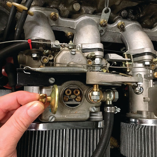
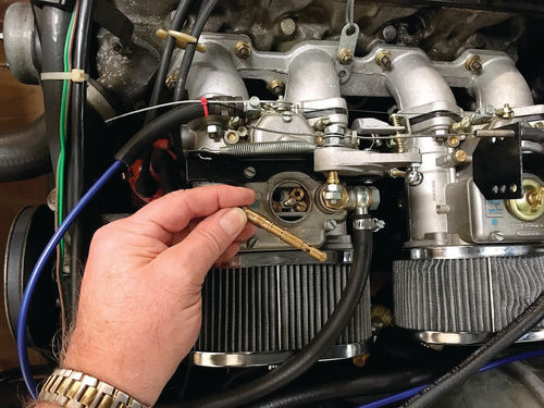
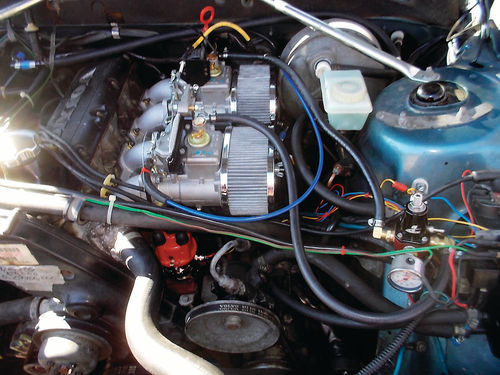
Why pick such a delicate and intricate package to power the Old Buster? Some would say “too much work.” Chuck Berry might say “too much monkey business.” But I would say why do people have old wind-up clocks? I have four in my house and they never chime at quite the same time. Why do teams of people struggle to keep a few Boeing B17s flying? There is something amazing about complex mechanical things. There is something interesting about knowing all that is going on in your car, especially if it is purely mechanical like a Weber carburetor (Photos 24, 25 and 26).
Preliminary Results on the Dynamometer
We ran our first autocross on March 26th and Buster drove really well. We had no problems and he felt more powerful. So on April 5th I took him back to EFI in Richmond for dynamometer tests. The results were:
1. It turned out that the in-dash AFR meter did not agree with the one in the tailpipe at EFI. We were too lean.
2. Aiming for a 13:1 AFR at full throttle, we changed the air correction jets to 180 from 200. We also switched from the 145 main jets to 150. Interesting that we now had the two jets that Trimning had guessed at and sent us along with the stock 45DCOE model 9 carbs.
3. On the 7th dyno pull, the peak HP was 119.73 (up 4.53) and max torque was 137.22 (up 6.80). The mix was average 12:1.
Testing Our Work on the Track
We ran two more autocross events, again with no problems. The car felt more powerful and ran like it should. But one nagging thought bothered me. The dynamometer graphs showed the Weber horsepower and torque dropped off at 5000 rpm+ and crossed the lines of the fuel injection system. Something was causing less power at high rpm. So we decided to prep Buster for some more Dyno work, this time without the air cleaners. The air cleaners are of a compact design and the flat lid comes quite close across the openings to the air horns behind them. I believe they are made for shorter air horns than we have.
So at the end of May, we repaired a small exhaust leak so we could trust the tailpipe O2 sensor.
Then we checked the timing with a strobe light. It was way off in the retarded direction by 10 degrees! I can’t remember or imagine why we didn’t check this earlier. It was just overlooked. Mistakes like this can leave you scratching your head, when the situation should have been handled with an obvious, necessary check.
Back to the Dynamometer for Another Look
When we arrived at EFI for another test, the weather was warmer and we went back to 145 main jets. Steve Williams at EFI was happy with the fuel mix at WOT. He helped us dial in the spark and we ended the session with the curve shown in Photo 27. The curve includes a dip to stabilize the idle and a second dip to quell some pinging.
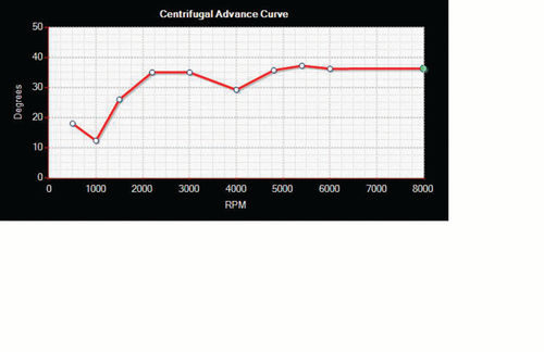
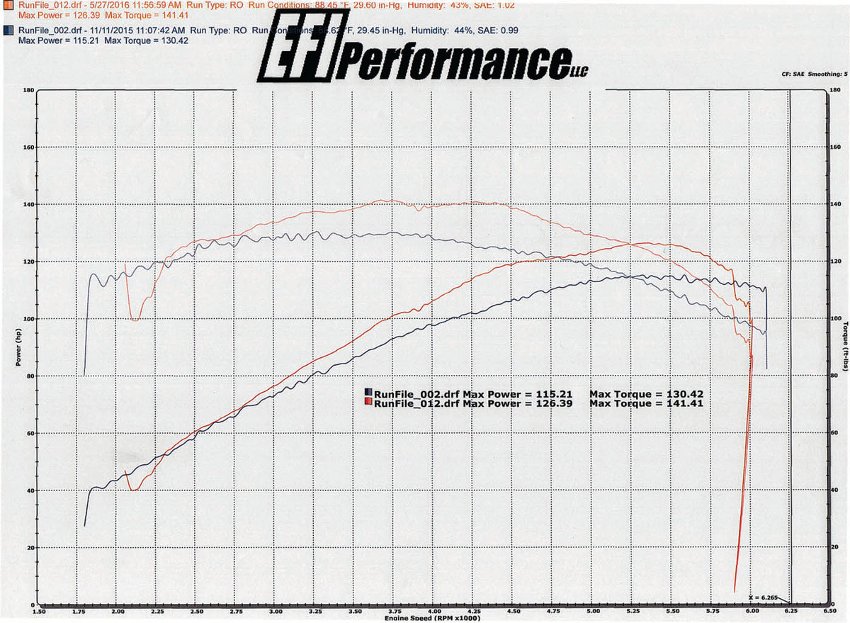
Photo 28 shows the best pull with Fuel injection (Run 2) and the best pull on the Webers (Run 12). There is an unexplained anomaly at max rpm that did not appear on any of the other graphs. Altogether, tuning Buster took 12 dynamometer pulls, but we ended up with gains of 11 HP and 11 ft.-lb. of torque. Buster runs great, feels stronger, and sounds good too.
Run 2 on 11/11/15. Max Power…115.21; Max Torque…130.42
Run 12 on 5/27/16. Max Power…126.39; Max Torque…141.41
For Us, It Was Worth the Time and Effort
I suppose it could be said that with the right test equipment and an expensive fuel injection system, we could accomplish the same thing, but this was an experiment on an old car and it worked (Photo 29). Mainly, it was an interesting journey and we learned a lot along the way. Remember, we could make no changes to the engine itself to improve our performance. Here is a link to the Youtube video of Run 12: https://www.youtube.com/ watch?v=QT3YM882qQQ
Resources
EFI Performance, LLC 4104a Eubank Road Richmond, VA 23231 efi-performance.com
KGTrimning Sandby 412 Lindegård 247 34 Södra Sandby SWEDEN | kgtrimning.com
Pegasus Auto Racing Supplies CarburetorJets 2475 South 179th St. New Berlin, WI 53146 | pegasusautoracing.com
Summit Racing Equipment Innovate Motorsports AFR meter summitracing.com
Weber Carbs Direct Carburetor Jets 20 Constance Ct. Hauppauge, NY 11788 Europartsdirect.com
Weber Carburetors manual by Pat Braden HPBooks ISBN 0-89586-377-4


