Replacing Fuel Injection With Carburetors
We’ll Move the Carburetor Components From the Test Car to the Project Vehicle, Install a Vacuum Pump and Take a First Drive.
In the first part of this series I described the project steps for switching Buster, our 1986 autocross Volvo 245, from Bosch Jetronic LH 2.2 fuel injection to Weber carburetors. We also established a baseline on a chassis dynamometer. In the second installment I described steps 2 through 5 listed below as they were performed on a test mule named Dino, a $300 1985 Volvo 244.
We ended with Photo 18 last time so we’ll pick up here with Photo 19. For a quick review, here are all of the steps involved:
1. Run the car on a chassis dynamometer to establish a baseline (completed).
2. Replace his intake manifold and throttle body with a manifold that interfaces with two 45DCOE Weber side-draft carburetors (completed on Dino).
3. Modify his fuel supply system to deliver gas at 3.5 PSI to the carburetors instead of 36 PSI to the fuel injectors. We must also remove control over his two fuel pumps from the Bosch 2.2 ECU and rewire them for manual operation (completed on Dino).
4. Replace his present throttle linkage with a suitable setup (completed on Dino).
5. Replace his distributor and Chrysler ignition controller with a new programmable 123Tune distributor made by Albertronic in the Netherlands (completed on Dino).
6. Install an electric vacuum pump to power the brake booster and HVAC control vanes.
7. Remove any remaining under-hood items that are no longer required.
8. Run the car on the same chassis dynamometer and tune the induction and ignition systems for optimum performance. I’ll begin this article with a description of moving the new components from the test mule to Buster. Then we’ll carry on with Steps 6 and 7, and also set the stage for Step 8.
Move Over to Buster
As we saw last time, Dino was running well with the new Weber setup. Therefore, moving it all over to Buster should be simple, right? Just unbolt and re-bolt. And so it was, except for one small thing. For unknown reasons the engine is in a bit of a different position in Buster than in Dino. I think it was because Buster has newer motor mounts than Dino’s which are collapsed a bit on the right side. That side takes the torque of the engine. But the difference meant that in Buster, the rear Weber air filter housing came within ¼-inch of the brake booster housing. This is just too close because the motor shifts to the left when lifting the throttle, especially in low gear.
While reading about motor mounts in the manual it stated that there may be shims between the mount and the front cross member. I have never seen shims used there before in the many 240s I have worked on. So what we needed to do was to shim the left mount up higher to tilt the motor away from the brake booster. Without a standard shim available I used two shims that were from a transmission crossmember. These were about 10mm thick and had notches cut in them so they could be slipped into place around the studs that penetrate the crossmember. This worked very well and the gap increased to about ½-inch clearance for the air cleaner.
I made permanent the changes to the fuel system and included a dashmounted cutout switch with indicator light for the fuel pumps, so you can have the ignition on without the fuel pumps. I also made permanent a dashmounted “choke” cable to operate the enrichment circuits on the two carbs.
I must say that when doing everything for the second time, I could do it better, more neatly, and in a more-refined manner. It was definitely worthwhile to first install the parts in Dino. So without having encountered anything else noteworthy on the switch-over to Buster I set off on the next step.
Step 6. Install a Vacuum Pump
Because the specialty intake manifold has no inter-connection between the 4 short runners, there was really no place to pull vacuum out for the HVAC control vanes and the brake vacuum servo.
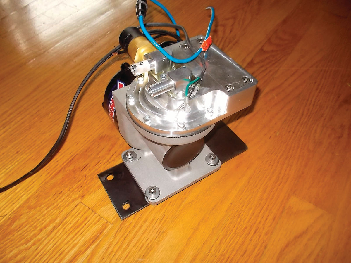
Fortunately, I was able to turn again to the after-market hot rod parts suppliers for a solution. From Summit Racing we ordered part number SUM 760152, an electric vacuum pump made for this purpose. This item is a combination of an electric motor, a diaphragm vacuum pump, and a regulating cut-off switch. Together they maintain a vacuum of 15 inches by switching the pump on and off. It is designed to provide vacuum for diesels and for cars with very radical cams.
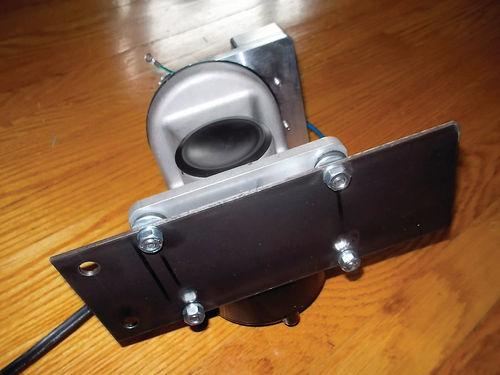
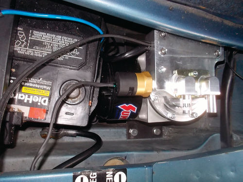
Except for the motor, the pump is made of machined billet aluminum and although it is fairly bulky, it is not too heavy. I found an ideal spot to mount it in the same spare tire well as the battery in the far back right corner of the wagon. I used a flat piece of 1/8 inch steel stock to make a platform in the well and attached the pump to this rectangle with the bolts provided (Photo 19). The kit provides for a rubber mounting using four grommets to absorb vibration (Photo 20). This location kept the weight down low and away from dirt, oil and heat (Photo 21).

I used another ISO-type relay to operate the vacuum pump remotely. I connected it directly to the nearby battery through a fuse (provided in the kit) but wired in the relay with the coil energized by fused ignition voltage through, first, a dash-mounted cutout switch and indicator light, and then the vacuum cutout switch in the pump assembly. I chose 1/2-inch PEX plumbing pipe and fittings to bring the vacuum up to the front of the car and through the firewall (Photo 22). The piping runs under the carpet right next to the right door sills.
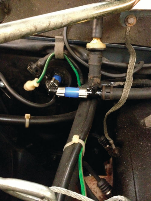
I put in a “T” connector for the HVAC connection and then used the rubber hose supplied in the pump kit to connect to the brake servo. This setup worked perfectly except that the pump operation is pretty loud. The thing is, everything about Buster is loud so it is just another noise. I don’t know of a quieter solution to this but I would not recommend this vacuum source for a boulevard cruiser unless it had straight pipes or a deaf driver.
Step 7. Removal of Unused Parts
This work was handled for the most part back in Step 2, but there is more to be done. The fuel injection wiring is still all there, just bundled together with strap ties for neatness. All the unused tubing is gone. The bulky air filter is gone. At some point when the Webers are off for any reason, I will remove the old wiring by unbundling it and then re-bundle the few wires that are still needed. To do this correctly, one needs an accurate wiring diagram, which we have.
Prep for Step 8. Coarse Tuning and a First Drive
It is time to tune. I read an authoritative book (see Resources) before I began this project and I went back and re-read the troubleshooting section again. Here are the basics that I learned from the book. There are four fuel/air circuits in the 45DCOE.
1. Idle
2. Progression
3. Main
4. Accelerator Pump
The idle circuit has one adjustable fuel needle for each barrel and this is mixed with air allowed past the throttle plates by the one adjustable throttle stop. Earlier, I explained that the Webers were simple to adjust for balance between the two carburetors and setting the idle was easy. For balancing I mean getting both pairs of throttle butterflies synchronized. The firing order of an in-line 4 is 1-3-4-2. So the front carburetor operates the first two cylinders to fire (2, 1) if you start with #2- (like 2, 1, 3, 4), and the rear carburetor supplies the next two (3, 4). There is one screw that changes the relative position of the two pairs of butterflies, and one screw that is the single throttle stop adjustment point. By carefully setting these two screws, and by listening to the engine running only on cylinders 2 and 1 (sounds like a Harley) and then changing the screw to make it run on only 3 and 4, it is simple to find the balance point in between just by listening for the rhythm to smooth out into four even pulses.
After I had the balance straight and the idle speed at 800 rpm, the next step was to drive the car. I never changed the idle fuel needles. I simply ran them all in to the stop and observed the rotation of each. I averaged the four rotations and then set them all the same. This was really unnecessary as they ended up approximately where they were “out of the box.”
What I found on the first drive was that, like the idle, full throttle seemed to be good “out of the box” but the transition from closed to open throttle was rough with coughing, misfiring, and spitting back. This realm of engine operation, low speed, low power, and throttle movement is controlled by the progression circuit and the accelerator pump. The steady state, low speed, low power is controlled by a progression jet for each barrel. This jet mixes fuel, metered through one hole, with air metered through another hole. This mix is fed into the throat through a progression of holes that are uncovered as the throttle butterfly plate opens. Making the fuel jet bigger makes the circuit richer and making the air hole bigger makes it leaner. This circuit has the biggest impact on the overall driveability of the car.
The accelerator pump circuit is controlled by two different jets. One of these is provided for each barrel and the other is called the bleed-back jet and is common to both conjoined barrels. More on this later.
So how close are we? Close enough to drive the car around and take it on the freeway.
Next I will cover the final tuning and the dynamometer pulls to see what we have accomplished.
Resources
Ferguson Plumbing Supply 505 Garrett St. Charlottesville, VA 22902
KGTrimning Sandby 412 Lindegård 247 34 Södra Sandby SWEDEN kgtrimning.com
Summit Racing Equipment Vacuum PumpP.O. Box 909 Akron, OH 44309-0909 | summitracing.com
“Weber Carburetors” by Pat Braden HPBooks; ISBN 0-89586-377-4 Available through: Moore Parts Source 3945 E. La Palma Ave. Anaheim, CA 92807 | mooreparts.com & Pegasus Auto Racing Supplies 2475 S. 179thSt. New Berlin WI 53146 | pegasusautoracing.com & Summit Racing Equipment (see information above)


