
Tuning Up A 1948 Packard
The Engine Had Been Rebuilt Yet It Backfired While Idling. It Took Some Searching, But the Culprit Was Found.
THIS 1948 Packard Custom Eight Convertible is receiving a complete “ground-up” restoration. All engine, frame and chassis components have been cleaned, replaced, overhauled and/or painted.
The Packard engine is a “marine”356- cubic-inch equipped with an Autolite distributor and a Carter WDO carburetor.
As you may know, this marine engine turned opposite (clockwise) to a standard car engine (counterclockwise)as viewed from the driver’s seat. The camshaft was replaced to make the engine run in the right direction.
The original engine had been replaced because of a cracked block that was not repairable.
A Concern
The engine was professionally rebuilt and the tune-up items were all-new or rebuilt. A new muffler system was installed. The distributor was tested and adjusted on a distributor machine, resulting in correct advance and firing.
The new engine would start right up and run smooth. However, when revved up in neutral, the engine backfired out the tailpipe. Furthermore, it was sluggish upon opening the throttle.
Our Approach to the Tune-Up
When tuning any engine, all components must be tested, adjusted and serviced to specifications.If you miss “step 18” in a “20-step tune-up” procedure, the engine may not perform as specified or expected.
Always, always tune engines to specifications and replace tune-up items with specified components. Even then, you must compare dimensions and performance to original equipment parts and specifications.
Our approach included testing the starting system, checking the engine cranking compression, servicing the ignition system, and checking the fuel supply and carburetor before startup. Then, we’ll start the engine and perform the running tune-up adjustments.
The Starting System
The + (positive) ground 6-volt starting system had new one-gauge heavy duty cables installed. The ground cable was connected to the engine.
The “rest” voltage was 6.6. The cranking voltage at the starter solenoid was 5.1. The ground voltage is 0.07 during crank.
This is all very good and the starter sounded energetic like the engine wanted to start right up. But not yet!
The Engine
New 20-50 wt oil and a filter element were previously installed.
The “dry” compression test was 80 psi on all 8 cylinders. This is good enough for startup.
The compression ratio on the engine is specified at 7:1. Compression pressures ideally should be up around 100 psi at sea level. However, with breathing (volumetric) efficiency calculated in, 80 psi is very good on this newly overhauled engine.
Ignition
New spark plugs had been installed during the overhaul. However, the spark plug inside porcelains were carbon black, but dry. This may have been caused by the backfiring experienced during rev up.
Black sooty porcelains can also be caused by rich carburetor mixtures.
New specified spark plugs (Autolite 3126) were gapped to 0.030-inch, installed, and torqued to 1/4 turn past washer seat contact.
Note: This 1/4 turn past washer seat contact is an “old time” specification for correct torque and sealing compression. “Tapered seat” spark plugs without washers (beginning around 1955 model engines) should be torqued to 1/16 turn past taper seat contact.
The ignition switch was tested by opening the points, turning on the key, and measuring the battery voltage. The voltage was 6.6, key on. Wiggling the key to simulate vibration yielded a steady 6.6 volts.Turning toward “off” resulted in a 1/8 turn before the voltage dropped to 0 from 6.6. Very good!
An ignition key switch test should be performed on all collectible vehicles at every tune-up.
Intermittent voltages during ignition switch tests will lead to ignition misfire.
As I experienced when tuning a ’40 Buick, the switch intermittently would show voltages from 6.3 to 0 when wiggling the key in the “on” position.
Please be aware that collectible car switches can deteriorate. In extreme cases, the old Bakelite insulation can crack leading to shorts and fire.
For safety, install a quick disconnect on the battery ground post. Disconnect the entire electrical system every time you park your collectible.
The points were gapped at 0.017-inch which is specification. The distributor cam had cam lube applied.
The points and ground (distributor base) measured 0.2 ohms (continuity).
This ground test is performed with the key off and points closed. Using a digital ohmmeter, hook up one lead to the engine (vacuum line, ground), and the other to the distributor terminal. The ohm reading should be zero (0). This measurement proves the points have good electrical contact and the ground circuit through the distributor to the engine isOK.
Next, open the points and measure the resistance using the highest scale on your digital ohmmeter.
Our Packard passed the point-open resistance test measuring over 20 megohms(20,000,000 ohms). This proves there are no direct shorts to ground. And the condenser is not shorted.
With the key off and the points open the coil primary ohms was 1.1. The 6- volt coil secondary measured 4850 ohms. This is in the ball park for a 6-volt coil.
Make sure the coil polarity is hooked up right. On a positive ground 6-volt system, the coil + primary terminal must be connected to the distributor primary terminal. The coil (-) terminal is connected to the ignition switch.
On our Packard the coil + was connected to the distributor primary terminal.
The wrong polarity will reduce coil available secondary voltage leading to ignition misfire under moderate cruising engine loads.
If the coil is not marked, Motor references show you how to determine coil polarity.
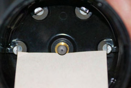
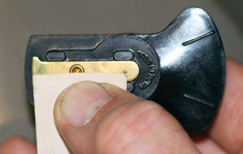
The rotor gap was measured using a gauge fabricated from a business card. See Photos 1 and 2.
The rotor gap was a whopping 1/8 inch! This gap must be 1/64 inch (0.015 inch) or less.
A large rotor gap leads to too much coil secondary voltage loss resulting in ignition misfire.
Upon inspection we discovered the Autolite rotor was for a 6-cylinder Packard engine instead of an 8-cylinder Packard. That was replaced.
The plug wires were new.
After all the ignition services, a “fat “ blue spark jumped out of the coil 1/2- inch during cranking with the key on! The coil output measured 30 kilovolts during cranking.
Don’t stop here when you discover a major cause for backfire. Continue the tune-up as other tune-up items may, and usually will, result in poor performance. The thorough tune-up will prove to you what’s right and/or what’s wrong.
The Fuel System
With new steel fuel lines and a new pump the pressure was 4 psi at the carburetor. This was measured with a vacuum-pressure gauge while cranking. The flow was good with strong squirts into a plastic bottle during cranking.
The Carter WDO carburetor choke was adjusted at the index mark and snapped shut when opening the throttle.
The choke pull off and the metering rod choke vacuum passages were open to both barrels in the carburetor base.
Note: Some makes of carburetors require a “slotted” base gasket to provide vacuum to the metering rods, power valve and/or the choke pull off.
The accelerator pump had a strong squirt.
Start-Up
Now that all the “preflight” tune-up items are completed, it’s a pretty good bet your collectible will start up within five seconds of beginning the cranking.
Our Packard is equipped with a carburetor throttle-operated starter switch. Turning on the key and opening the throttle to around 1/4, the engine started in two seconds!
The engine ran very smooth “right off the bat,” but sounded sluggish. After warm-up the choke was wide open, the engine ran smooth upon rev up. No backfire!
I hooked up an adjustable timing light to number 1 plug wire and a 12-volt auxiliary battery for power.
The base timing was retarded from specifications. It was adjusted to 6º BTC (before top center).
Revving it up to 2500 rpm steady state the advance, measured with the adjustable timing light, was 22º BTC.
The vacuum advance line at idle was 0 inches indicating “ported vacuum” in the carburetor at idle. At 2500 rpm the vacuum on this line was the same as manifold vacuum.
This ported vacuum line was then connected to the distributor. The advance was measured again at 2500 rpm. It was 39º BTC.
All these checks confirmed the mechanical and vacuum advance was operating as specified on our running engine.
The Autolite distributor (1GT 4203) specifications are 111⁄2° (distributor degrees) at 1800 rpm and 101⁄2° at 17 inches of vacuum. (From the Motor’s Auto Repair Manual.) These distributor advance specifications calculate to 23° crankshaft degrees mechanical advance (111⁄2 x 2) at 3600 engine rpm and 21° (101⁄2 x 2) crankshaft degrees vacuum advance at high (17”) manifold vacuum.
“Total” advance on the crankshaft is the sum of the mechanical, vacuum and base timing advance.
The total advance adds up to 21 + 23 + 6 = 50 crankshaft degrees at 3600 engine rpm.
The 3600 rpm measured in N is a little too much rpm in neutral on any engine. This is why I measured the total advance at 2500 rpm in neutral. As stated above I measured 39º total advances. Close enough to distributor specification through interpolation.
The manifold vacuum was 17 inches at 2500 rpm and increased up to 25 inches during a quick closure of the throttle from 2500 rpm. This indicates this new rebuilt engine is a good “air pump.”
The carburetor checks were also good at 2000 rpm steady state in neutral. I choked the carb slightly and the rpm increased to 2200 rpm maximum at the same throttle opening.
This test indicates the carburetor main circuit mixture was slightly lean. This result is OK.
There was no “drip” out the main discharge nozzles at 2500 rpm and at idle. This tells me the main mixture discharge is “smooth looking and even” on both barrels of the WDO Carter carburetor. And there’s no drips out of the accelerator pump circuit.
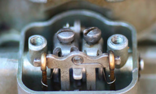
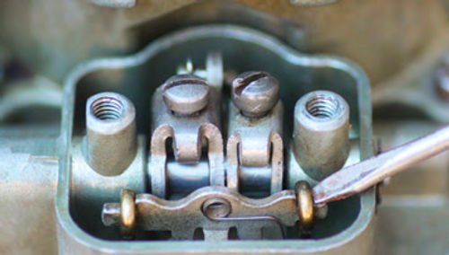
Also at idle and at 2500 rpm, the metering rods were “pulled in” by 17 inches of manifold vacuum, and would “lift up” upon a snapping of the throttle (low vacuum caused by sudden opening of the throttle). See Photos 3 and 4.
After these checks we adjusted the idle mixture at 500 rpm in neutral.
Start this adjustment by opening both idle screws to the rich side (3 turns from seated position, engine off).
With the engine idling, screw in one idle mixture screw watching for the “peak” idle rpm, then, continue turning the mixture screw inward (clockwise) until the lean point is reached (slight rpm drop and approaching a rough idle).
Then, turn this screw outward one complete turn (360º counterclockwise).
Adjust the other idle mixture screw using the same procedure. Now the idle mixture is balanced between the two barrels.
Following the idle mixture balance adjustments, choke the carburetor slightly at idle. If there’s no change in idle rpm, the idle mixture is “about right.”
If the rpm picks up slightly with a light choke, the mixture is slightly lean. Open both idle mixture screws equally 1/8 turn more and retest as above.
If the idle speed drops off a lot during a slight choke, screw both mixture screws inward 1/8 turn and repeat the above test.
You want to aim for around the middle between lean and rich on pre- emission control vehicles (pre-1966, first sold in California and pre-1968, first sold outside California).
Note: Later emission-controlled vehicles all have specified idle mixture procedures. Check your Motor references for specifications and procedures.
Results
Needless to say, the owner was elated with the smooth power during rev up and no backfire.
As I stated at the beginning of this write-up, it behooves you to make sure every tune-up item is at specification to assure good touring performance.
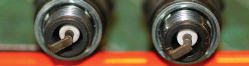
Just as a last check (icing on the cake), we removed two spark plugs. The inner porcelains were white; not black and sooty. This is pretty good proof the main carburetor circuit was OK and the back- fire was caused by a short distributor rotor (1/8-inch gap).
Had the main circuit mixture been real rich, the plug porcelains would have been sooty black after running for a very short time (Photo 5).
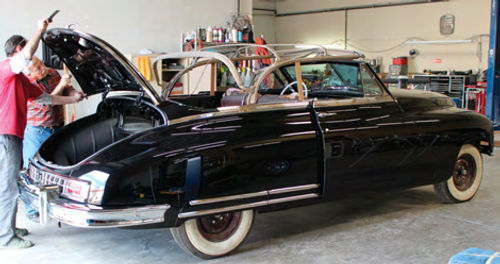
The next stop for this car (Photo 6) is the upholstery shop.


