Some Homemade Tools, Pt. 2
In His Ongoing Quest for Tools, He Buy sand Makes Them,Too. Here Are Three More From His Collection.
Editor’s note: Contributor John Armstrong is a self-confessed tool addict who often can be found wandering through hardware stores and swap meets looking for items to add to his collection. But in addition to buying tools, he likes to fashion useful ones in his shop as well. As he puts it: “Sometimes it may be an improvement on an existing tool that makes it more useful or better suited for your specific needs. It also can be a tool that’s no longer available for a particular task. It even can be a cost-saving measure, REALIZING the simplicity of a ‘production’ tool and choosing to make it yourself.” With that in mind, we featured three of John’s homemade tools in the December 2011 issue and here are three more. Since there were four photos in the first installment, we’ll start here with Photo 5.
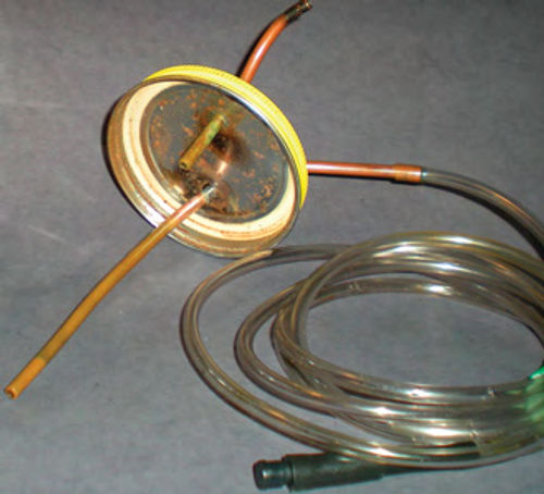
Vacuum Reservoir Jar. This jar with tubes and a hose coming out of its top in Photo 5 started life as a peanut butter jar about 30 years ago. With some properly placed copper tubing, hoses and a vacuum source, you now have a reservoir for collecting brake fluid, antifreeze, power steering and transmission fluid and more.
Start with a glass jar that has a screw on lid. I don’t believe anyone is still producing glass jars for peanut butter, so a Ball or Mason canning jar would be a good choice. A pasta sauce jar will also work as long as it is glass with a metal lid. (My mother has an endless supply of old screw-on lid jars, some quite vintage; maybe your mom does as well.)
In addition to the jar, you will need the following:
1. 2’ of 1/8” ID (3/16” OD) copper tubing.
2. 6’ of clear plastic aquarium hose. While you’re there also get a couple of the brass aquarium shutoff valves, you may find them useful later.
3. 1’ of 3/16” automotive vacuum hose.
To start, you’ll need to drill two holes in the lid, about 1” apart. The tubes will be soldered in place. There is, of course, some preparation before drilling and soldering.Clean off any paint from the outside of the lid in the area the holes will be drilled. Should the lid have some kind of seal in this area on the inside, carefully remove it. Use a utility knife, razor blade or whatever works best. Do not disturb the seal around the perimeter edge of the lid, however, as it must seal tightly.
When you drill the two holes in the lid make sure they allow the copper tubing to fitsnugly through. Place the lid on the jar and insert one section of the copper tubing through either hole until it is about 1/2” from the bottom of the jar.
Next, cut off any excess copper tubing, leaving only a couple of inches remaining outside the lid. Repeat this procedure with the other hole but this time only insert the copper tubing inside the lid for about 1”. Use some fine steel wool to clean up the portions of the copper tubing where they meet the jar lid in preparation for soldering. Then you are ready to solder. The lid can be left on for this procedure, but there is always a chance of cracking the glass jar. Another option would be to use a vise to support the lid with the vise jaws slightly open (allowing clearance for the copper tubes). Use rosin core solder, and a high-wattage soldering iron. A better choice would be to use a propane torch with a low flame. Solder completely around each tube to ensure a complete seal. Photo 6 shows the appearance of the inside of the lid once the soldering is complete along with the relative lengths of the copper tubing.
The aquarium hose is connected to the tube that extends almost to the bottom of the jar. This is the fluid line. For brake bleeding insert a 1” section of copper tubing into the opposite end of the hose and onto that a short piece of vacuum hose. This will stretch and fit over the bleeder tip on the wheel cylinders and calipers. You may notice in the photos there is a plug in the end of the “bleeder tip.”This Is only to avoid making a mess from any residual fluid dripping out of the aquarium hose.
The other copper tube is connected to the vacuum source. As long as the jar doesn’t get overfilled or tipped over, no fluid will be drawn into the vacuum source. Vacuum is typically applied with a hand pump or a pump for air conditioning service. If you have access to one of these pumps, simply modify the end of an old hose, and it could do the work for you. Engine manifold vacuum also could be used as the source, but depending on the task being performed you may choose to use a second vehicle as a source. For example, you wouldn’t want to have the same vehicle with its engine running supplying vacuum while sucking the fluid out of its power steering pump.
This tool is extremely handy when flushing out old brake fluid. This is a good service to perform every couple of years to help reduce the chances of rust in the system from moisture. Start by taking the top off the master cylinder and placing the fluid hose into the bottom. Apply vacuum and let it remove all the old fluid. If the master cylinder has two reservoirs, repeat this process with the second. Next refill it with fresh fluid and you’re ready to start bleeding the system. Remember to watch and maintain the master cylinder’s fluid level (or have a helper do so) to avoid accidentally pulling air into the system. Typically start with the wheel furthest from the master cylinder and when the fluid is clean looking (this is where the clear fluid hose is helpful), move to the next wheel for bleeding. You may see bubbles in the fluid stream that are actually air coming in around the bleeder threads. Don’t get excited, these are not getting into the system, but it can be misleading. What I have done to eliminate (or greatly reduce) this is to remove each bleeder screw and wrap the threads with Teflon tape. When opening the bleeder, do so only enough to establish a good flow of brake fluid and you won’t get any false signs of air in the system. Once satisfied a “wheel” is clean and free of air, close the bleeder screw and then remove the hose from the bleeder. Remaining vacuum in the jar will then pull in any fluid that is in the line.
To be safe and avoid any possible contamination to other systems, use a dedicated fluid hose for each task (brake fluid, transmission fluid, antifreeze, etc). Emptying the jar frequently is a good idea. This will make it easier to judge how clean the brake fluid is.
Brake Pedal Lock. This is not an everyday need for most of us, but it’s a handy tool to have. I use mine when I do a front wheel alignment, or need to re-torque the wheels after performing some service to them. In addition, it’s also useful for checking your:
1. Brake lights.
2. Searching for a wiring problem that requires the pedal to be depressed for any length of time.
3. Checking each wheel to see that all are locking properly. This is useful in detecting slippage which could be an indication of a wheel cylinder or even a master cylinder failing; a flexible hose that is badly restricting or totally blocking fluid travel to the wheel(s); or liningsthat are so badly contaminated that there is not enough friction to lock the drum.
4. Inspecting the front suspension. It allows you to grab onto the tire and use it for leverage, trying to rotate it back and forth. This will eliminate the ability to judge looseness in the wheel bearings, but that can be checked when the pedal has been released. With the vehicle properly supported for safety (using jack stands) and inspection of its particular suspension, this will aid you in the inspection of hard-to-see bushings, worn bolts, etc., but keep in mind that a second set of eyes is very helpful.
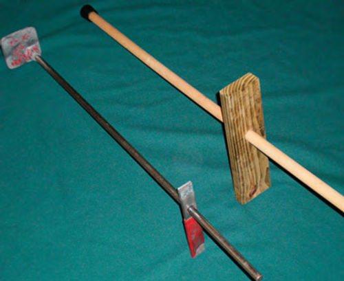
A brake pedal lock is constructed of a shaft that is used to press down on the pedal, and a second piece that slides on it and wedges against the forward edge of the seat to lock it. This type of tool is available new from professional tool distributors, but rather expensive for what it is. I was lucky enough to find one at a local flea market for a reasonable price, but making one is easy and you may already have the components on hand that will be needed. It can be made from metal, wood or even a combination of both. Even a section of 1/2” or 3/4” metal conduit(electrical metallic tubing or EMT) could be used as the shaft. The choice of material usually depends on what scrap items you have laying around.
Wood will do a good job of making a pedal lock, and is easy to work with. Start with a 30”-36” length of 3/4” wooden dowel. (An old broom handle would also do the job). If it turns out to be too long, it can be cut later. Get a rubber tip to put onto the end of the dowel where it will be in contact with the brake pedal. This will keep it from slipping off. These are sometimes sold as tips for canes or in packages of four to go on chair legs and come in various sizes.
Next you will need a piece of wood 1”x 3”x 10”. Measure up about 4” from either end and in the center use a hole saw to make the proper size hole for the dowel to fit through. It should slide up and down the dowel easily, but it can’t be loose. I used a section of 3/4” dowel and a 3/4” hole saw and the fit was perfect. You have now created the locking portion of the tool. Photo 7 shows the production version at the bottom, and the homemade version above it.
If desired, go a step further and cover the section of wood that wedges up against the seat to protect the seat covering. Glue on some fabric or vinyl; even some tool box drawer liner would do a good job.
Accelerator Pedal Depressor. An adjustable tool for depressing the accelerator pedal is handy too. You could fiddle around and probably get the brake lock to suffice, but it won’t be that easy to get the engine rpm exactly where you want them.
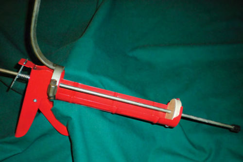
Instead, consider purchasing an inexpensive caulk gun and making a few modifications. Photo 8 shows the finished tool. I purchased this caulk gun at Walmart for $2. To make this work, replace the original caulk push rod with a length of metal drill rod of the same diameter.In this case that’s 1/4”.This can be purchased at your local hardware or home improvement store and will become your pedal depressor. A length of 30” is normally sufficient. If necessary it can be shortened when the project is completed. I first experimented with a wooden dowel as an option, but the locking mechanism of the caulk gun started chewing it up. It was obvious it wouldn’t last long before it would start to slip.
To get started, unthread the 5/16” nut on the end of the rod and remove the metal disc that would normally push the caulk. If needed, the disc can be removed by cutting the rod with a hacksaw. Now the push rod can be removed. As The caulk push rod is being removed, followit with the new “pedal depressor” rod. Hold down the release lever and actually use the new rod to push the old one out. If this is done carefully nothing will fall out except the old rod, but to be safe note the position of the spring and mechanism inside the handle justin case.
Next, a guide is needed at the front of the gun for our new pedal depressor. I used a 2 1 ⁄8” diameter hole saw to cut out a section of plywood. The plug that was removed from inside the saw blade was almost perfect. I enlarged the pilot hole with a 17/64” drill bit. This can be secured in the front of the gun with a couple of small screws or even silicone adhesive. The final step was to form something to press up against the forward edge of the seat. I found a piece of flat metal used in a chain link fence; bent it, cut it, and secured it using a radiator hose clamp. There is minimal pressure against the seat, so I didn’t worry about covering it, but a section of foam water pipe insulation or even rubber heater hose could easily be slid over it.
Finally, I pushed a small section of 1/4” fuel line hose on the end of the pedal depressor. This works fine for accelerator pedals that are “hinged” at the base and secured to the floor. For the later “floating” style pedal you would want a larger “foot” on the depressor. A quick and easy solution is to cut out a second plug with your hole saw. The original 1/4” pilot hole will already be a snug fit so just use a bit of silicone to secure it and you’re done.