
Some Homemade Tools, Pt. 4
This One Performs Continuity Checks on Armatures & Windings. Make One With Parts From the Hardware Store.
Editor’s note: Auto Restorer contributor John Armstrong is not only in the habit of buying tools on a regular basis, he also crafts them in his shop. We’ve featured John’s homemade tools in the December 2011 issue and this year’s April and June issues. Since there have been 11 photos in the first three installments, we’ll start here with Photo 12.
AC Current Tester
A test light and 12V battery, or even a volt/ohm meter can be used for checking continuity. These work well for many vehicle checks, and are perfect for testing delicate itemslike diodes. AC power, on the other hand, gives a little more “punch” than DC current, and is preferred for performing continuity checks on “heavy” things like armatures, windings and mechanical switches. When rebuilding a starter, generator or alternator, there are a number of simple checks that need to be made for “opens” or “grounds,” and that’s why most armature growlers include an AC current tester, but not all of them do. So if you don’t have a tester, here’s how to make one.

Typically these testers utilize a standard household light bulb socket, where a low-wattage bulb (usually 7 1 ⁄2 watts) is used as an indicator. Their construction is simple. In the most basic form the bulb’s socket has one of the power supply wires connected to one terminal, and its other terminal is connected to a wire with a test probe on the end. The remaining power supply wire is connected to one terminal of a switch, and the remaining switch terminal is connected to a second wire with a test probe on the end.
As to the question of polarity, it really isn’t an issue here. Most old armature growlers didn’t have a third ground wire in the power cord, or even a polarity type plug. So you might plug it into the outlet in one direction, and then the next time you used it, the plug might be reversed and you would never be aware of it.
In the construction of my tester, I made a slight variation from the basic approach. First, I had all the items I included already lying around my house and shop. And second, by using a small night light as an indicator it made this tester much more compact. But even if you go and purchase all of these items new, the cost is minimal, probably around $15. The most expensive thing will be your power cord.
The Parts List
Here are the basics that you will need:
1. Plug-in night light with a 4-watt bulb. 2. A 4” square standard household receptacle box to hold both a switch and outlet. 3. Wire clamp to fit into the electrical box. 4. Standard household light switch. 5. Standard household outlet (receptacle). 6. Faceplate to cover the switch/outlet combination. 7. Power supply cord with a plug on the end. (A light duty cord is fine for this.) 8. 5’ of 16- (or 18-) gauge two-conductor (stranded) wire for the test leads. (Basically lamp cord, speaker wire, etc.) 9. Two large nails and some vacuum hose to construct the test probes and insulators. 10. Other miscellaneous items: heat shrink tubing; (1) wire twist;(2) 6” lengths of solid copper ground wire. (The copper ground wire came from a short section of “ROMAX”; the flat wiring used in the walls of your home. I used 12-gauge wire, but for this project, virtually any gauge will work.)
Necessary Tools for the Project
Tools used are a screwdriver, needle nose pliers, a propane torch for soldering and rosin core solder.
Assembling the Tester
A. Start by removing one of the knockouts in the receptacle box and installing the wire clamp.
B. Next feed both the power cord and wires for the test leads in through the wire clamp. I used a short section of wire loom to help keep the wires bunched together. Allow about 6-8” of wire inside the box to work with. Now snug down the wire clamp. Photo 12 shows the results to this point.
C. The Green wire from the power cord is the ground connection and is connected to the ground screws (usually also green in color) of both the switch and outlet. This is accomplished using two short sections of solid copper ground wire to connect to both, and then all three wires are united using a wire twist.
D. The Black power supply wire is then connected to either screw on the side of the outlet with the narrower receptacle slots. These screws are usually gold in color. On the opposite side (with the wide receptacle slots) the screws are usually silver. Connect either test lead wire to one of these screws.
E. The White power supply wire is connected to either terminal on the switch, and the remaining terminal is connected to the other test lead wire. Photo 13 gives you a view of the wiring before it’s all stuffed into the box. I used terminal connectors on the stranded wires for neatness, but it’s not necessary. The two wires with Red terminal ends are the test leads. The Black (hot) wire is connected to the opposite side of the outlet, not visible in this image. (While the black wire seems to line up with the screw on the visible side of the outlet in Photo 13, it actually runs under the outlet to the other side.)
F. Push the wires into the box, making sure the copper ground wires don’t contact any of the other connections. Now secure the outlet and switch to the box. The faceplate can now be put on.

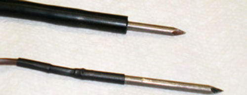

G. Test leads are made from large nails (probably #10 or #12), with the heads removed. Use a bench grinder, file or other abrasive and clean up 3/4” of the freshly cut end. Make certain that any galvanized finish has been removed in this area. Before going any further, it’s a good idea to slide the vacuum hoses over both test wires prior to soldering the nails in position. These will become the test lead insulators. First determine which size of vacuum hose will best fit the nail; usually it’s 5/32” or 3/16”. You want it snug, but must be able to slide it over the nail easily enough. A length of about 3” generally is good, but if you’re not sure, leave extra; it can be trimmed later. The hose(s) will slide freely over each wire, and it is easier sliding it down over the soon-to-be soldered joint and then the nail as opposed to going the opposite direction. Using Rosin core solder,solder each test lead to each nail as seen in Photo 14. I used a propane torch, but a powerful soldering gun will also work. Once cool, the soldered joint is covered with heat shrink tubing and the vacuum hoses are slid down, completely covering from above the soldered joint to the tip of the nail. To help make sliding the vacuum hoses easier, consider using a light coat of silicone sealant prior to sliding the hose in place. This will act as a lubricant initially and once cured, will also act as additional insulation.
Photo 15 shows the progression of the test lead construction. The vacuum hose in the top of the photo is not fully in position. The end result should have only the point of the nail remaining un-insulated; this will lessen the chance of accidental contact and getting shocked. Small diameter wooden dowels also can be used for insulators in place of rubber hose. Their length can be drilled through on a lathe, and the nail positioned inside, again using silicone, or something similar to secure the position. If desired, you can purchase pre-made test leads. These usually are available as replacements for meters and would require cutting off the ends that would normally connect to the meter. They will be connected inside the box. The exposed tips on these test probes are usually about an inch long, as they generally are used for probing for current, not delivering it. So for safety, cut the length of the tips to a maximum of 1/4”
H. Photo 16 shows the finished “test box,” with the night light in place. Remember to make sure the night light is switched on, then turn the box switch on and you’re ready to go.
While a metal receptacle box was used in this project, the plastic version might be the preferred choice. As mentioned above, this was made from what was on hand, but if purchasing the box new, plastic has the benefit of being non-conductive, and is less likely to scratch anything. When at the hardware store or home improvement center, explain that you want a box to hold both a switch and receptacle. They can show you the options.
Be Careful
Caution! Remember you are using AC current, and even with this very low wattage bulb, you can accidentally get shocked if you aren’t careful. When the switch is turned on, the test leads are hot! That’s why it’s important to leave only the very tips of the test probes exposed. If you plan to keep the tester on for any length of time, create an insulated wood (or other non-conductive material) “rest” to store the leads in between use. And don’t use this tool in a wet or damp environment.


