
OVERHAULING THE LAST OF THE QUADRAJET CARBURETORS PT. 6
We’re Going to Remove Large and Small Fuel Bowl Plugs and Then Mix Up Some Sealer For Their Replacements.
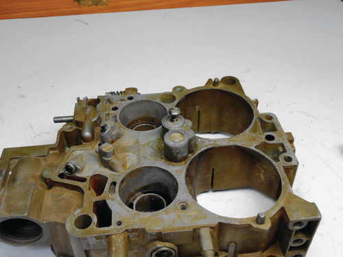
The swap meet carburetor fuel bowl will be the subject for the first round of plug replacement and resealing. Both the large and small plugs will all be replaced. If there are unexpected encounters or a learning curve, I would prefer it to be on this unit.
While there is no reason to expect any surprises, that’s why they’re called surprises! Photo 121 shows the two taps and the tap holders that will be used. To the left is the 10-32 and right is the 7 ⁄16"-20. Note the larger tap has a flat bottom; referred to as a bottom tap. This is what you need when doing the two large plugs, as there is a small shoulder inside below the plugs.
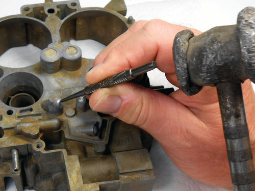
To get started, Photo 122 shows one of the small aluminum plugs being center punched. Sometimes it can be helpful to use a file and make several passes across the end to flatten it slightly. This can make it easier to target the center.
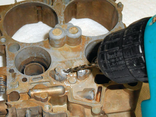
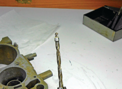
In Photo 123, as per the instructions a #29 (.136") drill bit is used to drill through the center of the plug. As an alternative, a 1 ⁄8" can be used. The aluminum is soft and drills easily, so if at the beginning the bit wanders or you notice you are slightly off target, the drill can be positioned at an angle to redirect it back to center. Proceed slowly and check frequently to make sure the bit is on center and follow the proper angle. As seen in Photo 124, when the bit was pulled out it had the inner shell around it. Photo 125 shows the cleared hole. This won’t always happen, but when it does you know the hole is clear and ready to be tapped. The small plugs that come in the “Bottom Plug Kit” require using a 10-32 tap, and that tap requires a .159" size hole, or the equivalent of a #21 size drill bit. If the hole is too small, the tap will never bite and start threading. A number drill set is by far the best choice to work with if the plug requires further drilling because each progressive number drill is only a few thousands of an inch different in size from the previous bit.
To put it all in perspective, there are 7 number drills in between the initial starting drill bit and the maximum size bit that can be used, while when using a fractional set there is only one bit. If you only have a fractional drill set you will be limited to a 9 ⁄64" (.140"), and then the maximum 5 ⁄32" (.157") drill bit. In that case, use the 9 ⁄64" bit to drill and remove the remains if needed. It should clear out any of the remaining aluminum plug.
In some cases you may see a curled up edge inside the hole. A pick tool may be all that’s needed to work at and remove that inner shell. Whatever drill set you are using, proceed slowly and with caution. You just want to remove the remnants of the plug, and not enlarge the existing hole in the bowl.
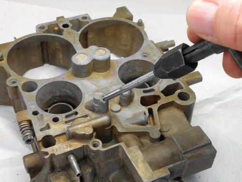
Next the 10-32 tap is aligned at the correct angle and threaded into the hole as shown in Photo 126.
If you’re not that familiar with using taps, here are a few tips: Always use oil to lubricate the tap. They make special cutting oils, but any oil is better than none. Square the tap up to the hole, checking it from several directions and once the tap has a firm bite and is cutting threads, stop about every ½ turn and rotate the tap backwards ¼ turn. This breaks off the chip that is being created from threading.
Note; the instructions stress to tap these small holes no deeper than 3 to 4 full turns. Once the tap is engaged and starting to cut, it can be backed out completely and then restarted to recount the threads; otherwise it’s difficult to be certain how many revolutions have been made. A 3⁄32" Allen wrench is used to test fit the plug in Photo 127.
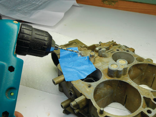
Photo 128 shows drilling another at a lower angle, but this time masking tape was applied to help keep the chips from entering into any of the small ports in the bowl. The bowl will be completely flushed with cleaner and blown out with compressed air when finished, but it never hurts to be a little proactive with masking tape. The four small plugs were all drilled and threaded in the same manner and then test-fitted.
Moving On to the Large Plugs
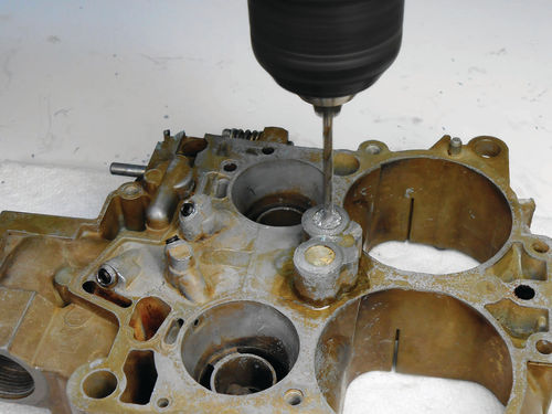

The large plugs are approached differently. Instead of drilling them out, they will be pulled out. A 1⁄8" hole is drilled in the center of one as seen in Photo 129. These plugs are fairly thick, so it may take more effort that you expect.
As per the instructions, an appropriatesize self-tapping sheet metal screw is threaded in as shown in Photo 130.
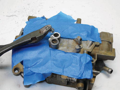
The instructions state to use a pair of wire cutters and pull out the plug as is being attempted in Photo 131. There was no movement at all, so Vise-Grips were attached to the screw in an attempt to cautiously wiggle it back and forth. Be careful not to apply too much force, because the last thing you want to do is break the screw off in the plug.
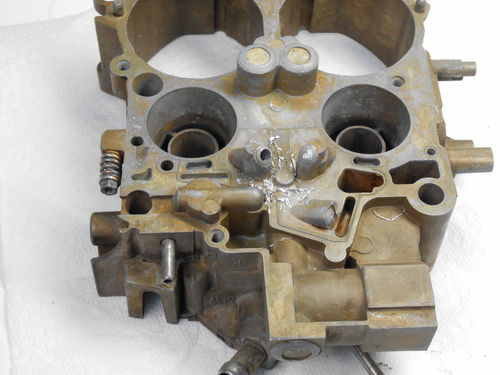
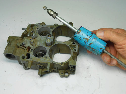
For us, it was still rock solid. There was an inexpensive slide hammer dent puller in my toolbox that utilized a sheet metal screw in the end. The first screw was removed, and the puller was threaded in. After three slides of the hammer, the plug came out as seen in Photo 132.

Well, while it worked, not everyone has one of these tools, so now what? In Photo 133 the remaining plug is being filed to remove that thick, rolled perimeter edge. It was filed until the file started to graze the casting as shown in Photo 134. A 1⁄8" hole was then drilled in this plug, and the sheet metal screw was threaded in. Again the side cutters were leveraged against the bowl, but this time they made easy work of removing the plug as you can see in Photo 135.
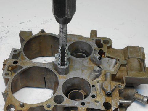
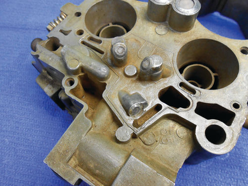
For uniformity the remaining perimeter edge of the first plug was also filed down to match. These holes are threaded with the 7 ⁄16-20 tap as seen in Photo 136. There is a small shoulder inside each hole that will limit how deep the tap can go, so when the tap bottoms, you’re done. Once both are tapped, the plugs are test-fitted. Photo 137 gives a view of all the plugs temporarily installed. Before mixing the epoxy and sealing them, all the passages will be cleaned to remove any traces of oil or small chips from drilling. The plugs will be dropped into the container of acetone to remove any possible oil or film.
Test-Fitting the Fuel Bowl
The thought occurred to me that the fuel bowl with the new plugs should be test fit to the throttle body before sealing them with epoxy.
After all, those two large bottom plugs definitely protrude farther than the original aluminum ones did. To my surprise, the bowl would not sit squarely down onto the throttle body. The depth of the well that the large plugs sit in was not enough to accommodate that added length. This was confirmed by a few bright marks inside the well that were created when the fuel bowl was wobbled around.
Then it occurred to me that the gasket had not been put in place before checking the fit. The gasket that goes between the bowl and throttle body is probably 1 ⁄8" thick, and this added dimension made the difference. As an additional safety margin, about 1 ⁄16" was ground from the top of each plug. When checking the height of the plugs and the depth of the well, it appeared that 1 ⁄16" was almost exactly the amount of clearance. While it probably wasn’t necessary, it will put my mind at rest. There is no question there will be a good seal between the bowl and throttle body. This is something worth remembering and checking, as there may be variations in the castings that could cause the plugs to fit differently.
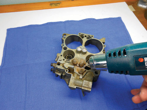
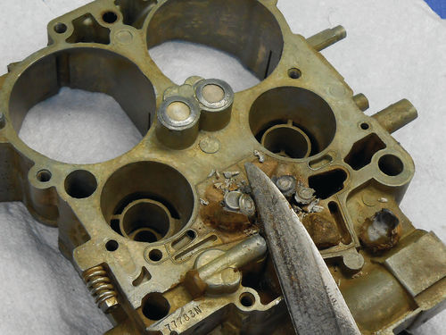
The only variant in the Caprice’s fuel bowl is the old epoxy coating on the four small plugs. It must be removed to be able to access those plugs, but it’s easy and doesn’t take much effort. Photo 138 shows the area being warmed with a heat gun to soften the old epoxy. After some heating, the knife was used to get under the edges and pop off the stuff as shown in Photo 139.
The end result is seen in Photo 140 after using a pick tool and then a small brass brush to finish cleaning things up. Now these small plugs will be drilled in the same manner as described above.
Looking Inside the Bowl and Preparing the Epoxy Sealer

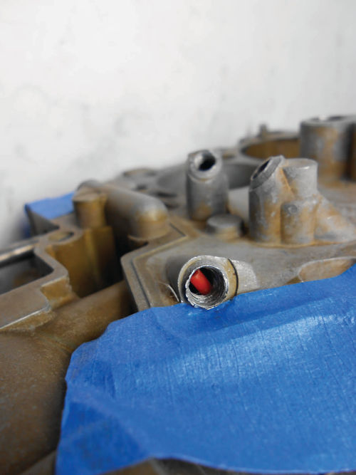
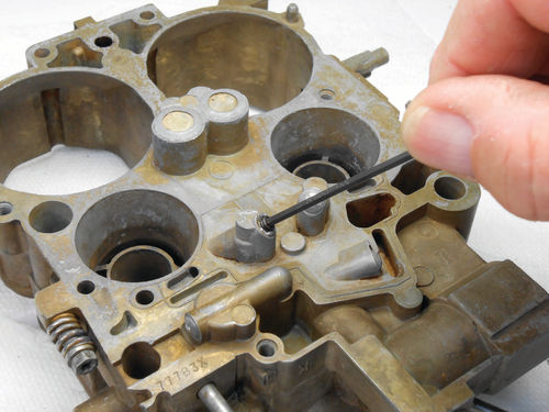
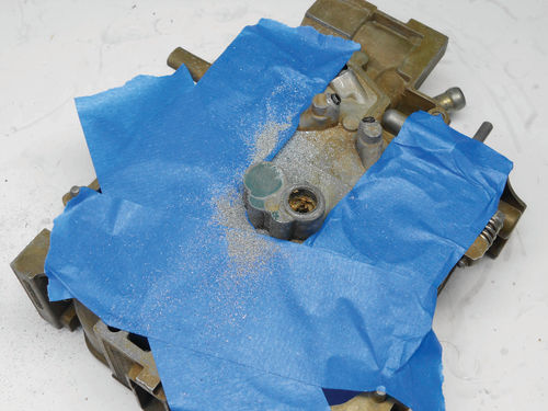
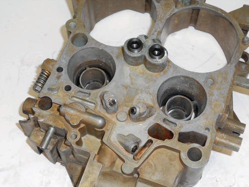
While the plugs are removed, you can take a moment to learn where some of those mysterious passages go and their functions. This can be done with compressed air, spray cleaner and in some cases by even inserting a red straw as is being done in Photo 141. Just slide it down one of the passages and see where or if it comes out. In this case here it is in Photo 142. This is the right-side accelerator pump discharge passage. Note how close this is to the new plug threads. If you were to thread the plug in until it stops, the red straw would be captured. Back it out 1½ turns and it’s free.
After replacing the plug fully and experimenting with both carburetor spray and compressed air, both appeared to flow through freely. So while the plug encroaches on the port, it doesn’t appear to noticeably restrict the flow.
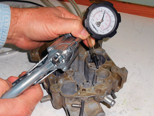
To carry the investigation a step further, a Mityvac hand pump was used to see if any pressure would momentarily build on the gauge as shown in Photo 143. It was tested in both the pressure and vacuum mode, and no pressure was indicated. While this might be considered primitive and of little value, if there were enough of a restriction, the gauge needle should show a slight bounce during the test. Being a “newcomer” to this procedure and just being cautious, it seems logical to at least do a few simple checks before sealing this plug in place. When this plug is installed and sealed, excess epoxy will be avoided.
Both fuel bowls will be sealed at the same time. The Marine-Tex epoxy instructions state that it starts to harden in 2-3 hours at 72° F, and will fully cure for structural applications in 18- 24 hours at 72° F. Also, pot life and cure time will be shorter at higher temperatures. So there will be no concern about the product starting to set before the task is completed. The instructions that come with the plug kit suggest warming the fuel bowl in front of an electric heater for a few minutes before applying the sealer. A heat gun or heat lamp are other options.
The accuracy of mixing the product is stressed. The ratio is 5 parts of resin to 1 part of the liquid hardener. There is an allowable margin for error of 10%. If the mixture is off slightly, the manufacturer states it’s preferable to use less hardener; too much can actually prevent proper hardening.
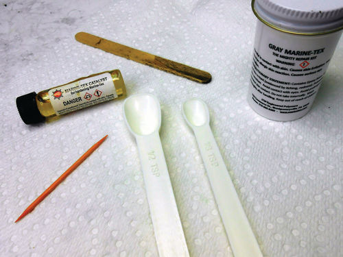
While my wife was willing to sacrifice a couple of tiny measuring spoons; I wasn’t. One trip to a thrift store and $1 later that problem was solved. A ½ TSP and 1 ⁄8 TSP will yield the 5 parts of resin, and the 1 ⁄8 TSP will be cleaned and then used to measure the hardener. In Photo 144 you can see what will be needed to measure, mix and apply the product. The wooden “ice cream” stick will be used to load the resin onto the measuring spoons, level them off and then unload the resin onto a paper plate. The spoons will be cleaned immediately, and then 1 ⁄8 TSP will be filled with the hardener and added to the mix.
The instructions state to mix together thoroughly, taking 2-3 minutes to do so until the consistency is equal. The resin is black and adding the hardener doesn’t change the color. A smooth, even lump-free consistency lets you know it’s completely mixed. This ice cream stick (called a craft stick at craft supply stores) serves one last function in mixing it all together. This resin is comparatively thick, and wants to hang onto the ice cream stick. The toothpick was used to scrape it off and assist in mixing.
Next we’ll apply the epoxy, install the plugs and start some of the reassembly work.


