OVERHAULING THE LAST OF THE QUADRAJET CARBURETORS PT. 8
Sometimes You Just Can’t Find the Tool You Need for Proper Adjustments. So You’ll Have to Make One.
Making a Mixture Control Solenoid Gauging Tool
Replacing the Mixture Control solenoid is simple enough, and will pretty much conclude the fuel bowl service once it’s properly adjusted. This is referred to as the lean mixture adjustment. A special gauge tool is required to properly adjust the solenoid. As of this time I have been unable to locate this tool either new or used. The factory manual shows it as #J33815-1BT8253-A. While not identified as such, this should be a Kent Moore tool. OTC lists a Computer Command Control (CCC) gauging set #7186 which would likely include both this MC solenoid gauging tool, and the gauge for the IABV adjustment. Finally try Thexton #370 and #403. The 370 should be both gauges, while I believe the 403 is only the MC solenoid gauging tool.
Without any success in locating these gauges, there is little choice but to make the gauge. Regardless of how you choose to make this gauge, a precision measuring tool; preferably a 1”–2” micrometer will be needed. One of those 0–6” digital calipers can be used if there is no other alternative, but it definitely isn’t as accurate.
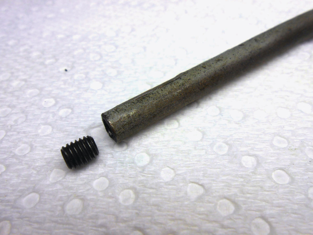
The length of the gauge is 1.304"; it’s hard to get too much more exact than that. In use the gauge is placed over the metering rod guide and sits on top of the jet. Images of the gauge (in the hard-to-see illustrations) make it appear slightly smaller in diameter than the base of the jet. A piece of scrap ¼" OD steel tubing looked promising to work with. It fit nicely over the metering rod guide, and is also slightly smaller than the jet. Possibly one of those extra 10- 32 set screws used to plug the fuel bowl could be threaded into the end making it easier to obtain that exact length. Photo 172 shows the material that will likely be used. The ID of the tube is .182", as gauged by a #14 drill. A 12-24 thread could easily be tapped into this diameter and work perfectly however it must not be a popular size, because there were no set screws at the local hardware store with that thread.
Instead, for the first attempt a 10- 32 set screw will be used, however while at the hardware store a couple were purchased that were longer, probably 3 ⁄8" long. The tubing was cleaned using the wire wheel on the bench grinder to remove paint and primer that was on it, and then cut with a tubing cutter. Both ends were cleaned up on a lathe, but the same could be accomplished using a file with patience to carefully level off the ends.
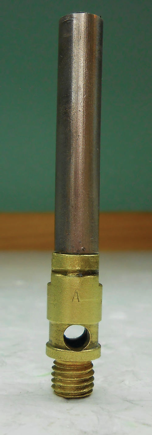
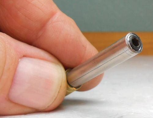
The tube was cut intentionally short, so that the set screw would determine the final length. Photo 173 shows it cut close to the needed length and sitting on the jet. The 10-32 screw just barely catches a thread at the end of the tube, so it isn’t secure, but it sure looks good in Photo 174. JB Weld epoxy was applied to the threads and carefully threaded in, leaving it several thousandths longer, about 1.312". Care must be used or the screw could fall inside the tube if threaded too deep or even from pressure when measuring with the micrometer. Should that happen; something would need to be inserted through the opposite end to apply upward pressure while threading it out slightly.
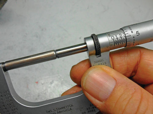
The next day with the epoxy cured, its length was trimmed on the lathe with numerous minimal cuts to avoid making it undersized. The final product is seen in Photo 175. Its diameter makes it blend in with the micrometer’s spindle and anvil. Had it ended up slightly short, a small amount of epoxy could have been added to the tip of the set screw, and then filed or sanded until the correct measurement was achieved.
Putting the Newly Made Lean Mixture Gauging Tool to Work
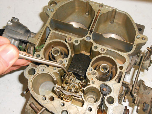
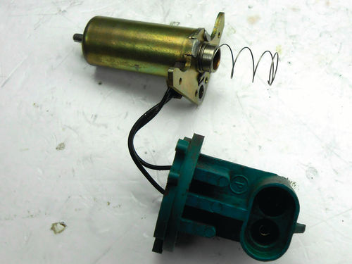
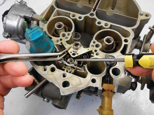
Lift out both the metering rods and their springs and set them aside for the time being. Now replace the float; needle and hinge pin. The float height has already been adjusted, so there is nothing additional to do here. In Photo 176 the solenoid return spring is being positioned in the fuel bowl. Photo 177 shows the proper orientation of the solenoid plunger return spring. It’s slightly larger at one end than the other. The smaller diameter of the spring should wind around the solenoid plunger stop as shown in the photo. A miniature screwdriver is helpful in getting the coil to wind around the stop. Don’t stretch it, just encourage it. If the spring is installed backwards, one of the coils can be trapped between the plunger and the stop when fully depressed. In Photo 178 the solenoid adjusting spring (also referred to as the lean mixture adjustment spring) is being pointed out and next the solenoid is positioned over it. The manual says to install the lean mixture gauging tool over the throttle side metering rod guide, so now is a good time to do that.
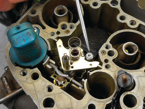
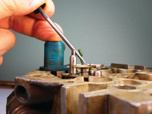
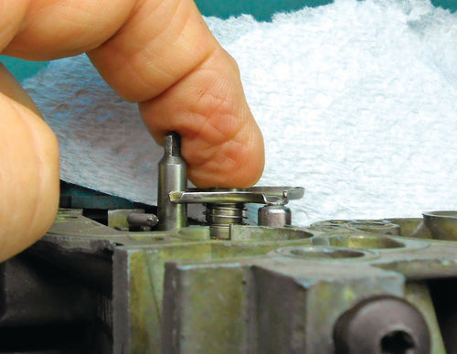
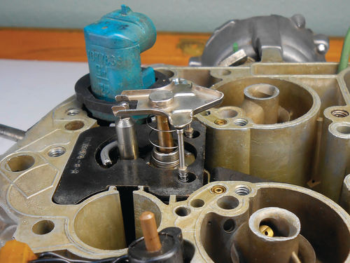
With the solenoid in position the lean mixture adjustment screw is initially tightened 6 turns. The solenoid wires are properly aligned and the connector secured with one screw. The pick is pointing to the gauging tool placed over the jet in Photo 179. Meanwhile, Photo 180 shows the plunger installed and bottomed against its stop (the TPS was temporarily removed for a better eyelevel view). There is no interference with the spring, and the plunger travels smoothly. The adjustment is made by rotating the lean mixture adjustment screw (it’s poking into my finger in Photo 181) while holding the plunger down The adjustment is correct when the plunger contacts both the solenoid stop and gauge. Use the special adjusting tool to turn the lean mixture screw until contact has been made with the gauge, and then reverse it slightly to break contact. Slowly work it back and forth reducing the amount of travel each time. This helps to make the adjustment as exact as possible. The paper towel in the background of the photo is a visual aid to make it easier to see when the plunger just contacts the tip of the gauge. The gauge can now be removed and set aside. If you had recorded the original position of the lean mixture adjusting screw during disassembly, now is the time to check your notes. From its new location slowly turn the adjusting screw clockwise and accurately count the number of turns it takes to lightly bottom, and write it down. Compare it to the number recorded initially, and if it is less than ¾ turn difference; the original position recorded is the correct adjustment. If greater, then use the new adjustment. This information was found in the GM products service training manual “1981–1988 Computer Command Control Carburetors” and a professional Motor manual. Keep your notes on this, and remember what the final adjustment was set at. There is an external access through the air horn for the lean mixture adjustment, and this might be of value should difficulties be encountered during the final adjustment. The Caprice carburetor will remain at gauge height because I neglected to reference the original screw location. Now the metering rods; their springs; float bowl insert, new rubber seal around the solenoid connector and TPS are installed as seen in Photo 182.
Here is an interesting note that was found in the Mitchell manual with regard to the MC “solenoid lean mixture screw (bench adjustment).”
“This is a preliminary adjustment only. It is required to ensure that the lean mixture screw is set close to specifications prior to the final adjustment. Final adjustment must be made with the carburetor installed and engine running. See appropriate TuneUp article.”
There was no additional information found in the manual regarding vehicle solenoid related adjustment. As each manual is year specific, I even checked a couple of years ahead, but nothing. There’s an almost identical note with regard to the rich stop adjustment. Nothing was found referencing any on vehicle adjustment in the Chevy factory manual, and it was practically examined page by page.
Returning the Air Horn After a Long Absence
There are a number of small tasks that need to be performed before the air horn will be installed on the fuel bowl. Let’s start by gaining access to the rich mixture (solenoid plunger stop) adjusting screw. There are two approaches to doing this. If you have the special tool needed (included in the #7667 OTC tools), it can be removed from the bottom side of the air horn by just fitting the tool over it and threading it out. The top of the adjusting screw is stuck in the access plug, and will likely require some wiggling to finally free it and the spring. The plug can then be knocked out from the bottom with a drift pin and hammer. While you’re doing that, go ahead and also knock out the access plug for the lean mixture adjustment screw. It’s located just below the rich mixture access plug. It’s possible that external access to the lean mixture screw won’t be needed, but the plug is easily replaced.

If you don’t have the needed tool to remove the rich mixture access plug, it can be center punched and then drilled with a 7 ⁄64" bit as seen in Photo 183. I must admit that the plug was thicker than anticipated and for a brief moment it had me wondering. The bit never actually broke through to the other side as the plug is snugly fit onto the adjuster. A tiny hole did appear in the bottom of the plug, and progression of the drill bit came to a halt. To remove the plug a sheet metal screw was threaded into it, and then a pair of side-cutting pliers was used to leverage it out against the edge of the air horn.

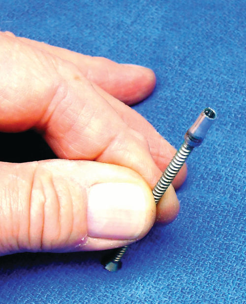
At first a sheet metal screw 1" long was installed, but it was too short to allow leveraging against the top of the air horn. Photo 184 shows a screw considerably longer, and while it certainly doesn’t need to be so long, this worked perfectly. The remnants of a paint stir stick was used for protection; eliminating any worry of damage to the air horn. Photo 185 shows the extracted plug on the end of that long screw. While here, now is a good time to make the suggested preadjustment of the rich mixture stop screw. If it was completely removed, replace it and its spring, and then bottom the screw. Now back it out ¼ turn.


There also is a plug over the TPS adjusting screw, and it will certainly be easier to remove now than when back on the vehicle. It was drilled in a similar manner, but a smaller drill bit and relatively tiny screw were used as shown in Photo 186. A wide-blade screwdriver was used to pry against the screw head and pop the plug out. Photo 187 shows that the plug length is about half of the one previously removed.
There are two small seals installed in the air horn; one for the accelerator pump shaft, and the other for the TPS actuator pin. If you’re thinking you don’t remember a seal around the accelerator pump shaft on older Quadrajet carburetors, you’re correct. Here’s what the 1981-88 GM CCC Carburetor manual has to say. “A pump plunger stem seal and TPS plunger seal are included in the air horn assembly to reduce the possibility of fuel vapor losses to meet evaporative emissions requirements.” So once again it’s emissions related.
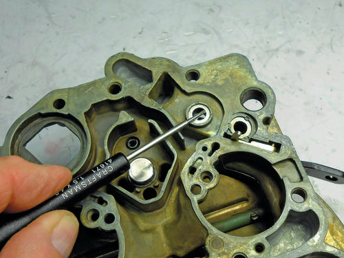

Both of these seals are backed with a washer which is retained by three equally spaced stakes in the casting. The factory manual says to pry out the old washer with a screwdriver as seen in Photo 188, followed by removing the seal. The washer is thin, and can easily be flexed and removed.
When installing the new seal, it’s installed lip side first so that the lip will be facing outside the carburetor. Here are the removed seal and washer in Photo 189. The manual goes on to say remove the old staking using a suitable tool, and after replacing the seal and washer re-stake it to retain the seal.
The thought of staking cast aluminum makes me cringe, something comparable to bending an ice cube with an ice pick. Even if all goes well there is a limit to how many times this can be done before another method must be used, or the air horn replaced.
My approach is a bit different. The seals are soft and pliable so there is no problem installing them with the stakes remaining. Instead of beating up on the air horn, the retaining washer was modified instead. A notch large enough to fit over one of the stakes was cut into the washer using a Dremel tool and cutoff wheel as shown in Photo 190. Any rough edges were then addressed with a small jeweler’s file. This allowed the thin washer to be flexed and an un-cut portion of the washer fit underneath one of the existing stakes.

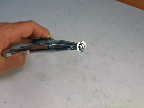

While pushing down on the washer with a small screwdriver it’s then grabbed on the inside and rotated with a pair of snap ring pliers like those seen in Photo 191. When the cut in the washer reaches one of the stakes, it allows the washer to be pushed down, and then rotated underneath it.
Eventually the entire washer was under the three stakes, and the notch rotated so that it was centered between two stakes as is pointed out in Photo 192. While this worked well, two properly spaced cuts would make it even easier. Using one of the casting stakes to hold the washer in position, then align the two washer cuts with the remaining stakes, push down and rotate, and you’re done. The next time service is required, replacing these small seals will be a breeze, and this washer could be reused. As a guide to making the cuts, center the washer on top of the three stakes and mark it with a Sharpie. Two cuts would seem to be the best number. A smooth-jaw hobby vise and jeweler’s file will also work well for making these cuts.
When looking through either carburetor kit no seal was found that properly fit the TPS pin. This is supposed to be for retaining vapors for emissions, so a reasonably snug fit was expected. This seal is smaller than the one used for the pump shaft, and so is the washer. What appeared to be the correct seal (green in color) was actually too loose and would drop down over the TPS pin. It didn’t seem like installing a new seal would make any improvement. Perhaps once installed the seal is compressed in some way and the fit will improve. After convincing myself to give it a try, the old washer was popped out in the same method, but this time one of the stakes broke off in the process. The bore was cleaned and the new green seal installed. The washer was notched as previously done for the pump shaft, and then set in place. While holding the washer down with a small screwdriver, a spring loaded center punch was used to create another stake to hold it in place.
So how did it turn out? The seal still fits loose as it did before installation. Well at least there’s no wondering “what if.”
Next, we’ll continue to replace and adjust the carburetor’s components.

