OVERHAULING THE LAST OF THE QUADRAJET CARBURETORS PT. 3
The Disassembly Continues As We Search for Components That Need Replacement.
Editor’s note: GM used the Quadrajet carburetor for a quarter century and the last versions, used in the 1980s, were designated as GM’s Computer Command Control carburetors. This series is covering the complex overhaul of one of those carbs. There have been 54 images so far and we’ll pick up here with Photo 55.
Continuing the Disassembly
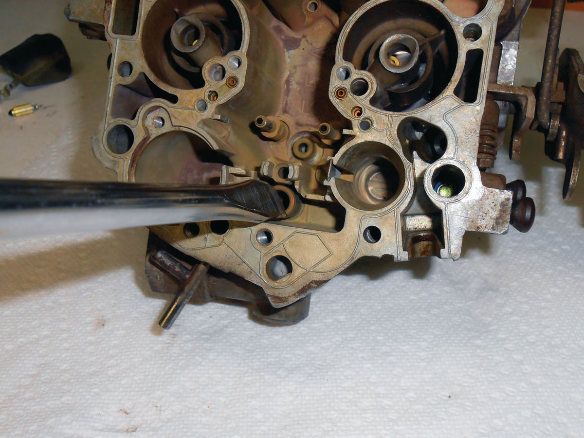
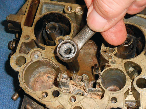
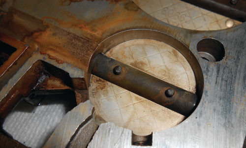
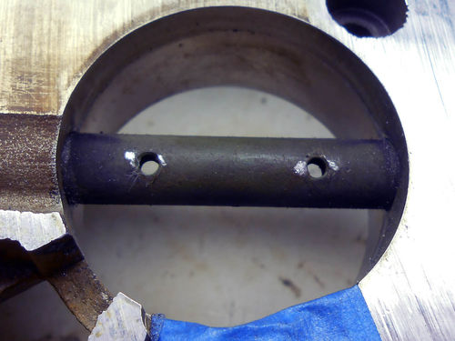
While those holes on either side in the metal float frame look inviting, definitely do not attempt to place the pull clip through either during reassembly. There is a special seat removing tool, but a large, wide, straight blade screwdriver easily removed the needle’s seat as seen in Photo 55. Beneath it is a small gasket that will likely remain in the bowl and must be removed; so grab that too.
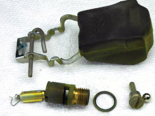
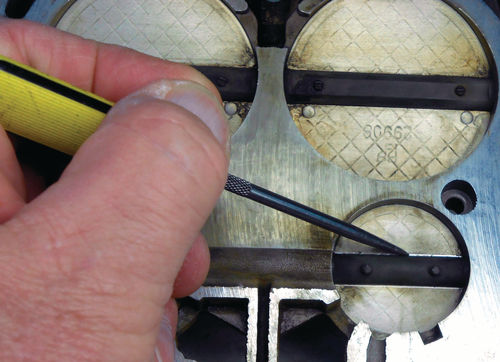
In Photo 56 a smaller straight blade screwdriver is used to remove the pump discharge retainer followed by the discharge ball. Save that old steel ball. It can be used to re-stake the discharge seat once all has been cleaned and it’s time to reassemble. Photo 57 shows a close view of the float with hinge pin, needle with pull clip, seat, gasket, pump discharge retainer and discharge ball. The only things still remaining in the fuel bowl are the two primary metering jets, and a thin metal baffle alongside the accelerator pump well. This is easily slid out to be cleaned with other small parts.
The jets are tall because of the guides for the metering rods; and a special tool is needed to remove them. You can either purchase one like that shown in Photo 12 by OTC tools (June) or make your own.
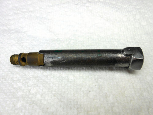

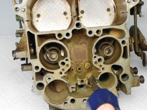
Find a section of small steel pipe that can be modified to slide over the metering rod guide and accommodate those two flats that measure 7mm. It’s easiest when you have one of the jets in hand to work with, but knowing that 7mm is the measurement allows you to make one without it. A small piece of pipe caught my attention in the “stuff worth holding onto tray” in the top of my crash cart. It’s just under 2" in length; the inside diameter is slightly under 7mm, and the wall thickness should be enough to yield the strength needed. A typical handheld electric grinder was used with a new wheel (to yield a squarer cut) measuring slightly less than ¼" in thickness; this should be pretty close. The small pipe was secured in the bench vise, and the hole in the pipe was used as a target to center up the wheel. Several passes were made through the center, and the fit was checked against the jet. When it was fairly close, a hand file was used to finish it off, and then it was taken over to the wire wheel on the bench grinder to remove any remaining burrs. Finally a nut was tack welded to the top as a means to rotate it. If you don’t have a welder, a notch could be cut into the top so that a large straight blade screw driver could be used instead. Here it is in Photo 58. More importantly, here it is removing those stubborn jets from the bowl of the swap meet carburetor in Photo 59. With these jets out, it will be considerably easier to remove that crusty residue in the fuel bowl seen in the photo. It’s worth mentioning that some of that heavy crud was ultimately removed using a Dremel tool with a wire wheel, and then the fuel bowl was submerged in a container of household white vinegar for about eight hours. I wasn’t sure what to expect or if it would help, but was amazed at the results as you can see in Photo 60. This doesn’t remove all contaminants, just that rusty moisture residue. So don’t cross carburetor cleaner off the list.
Things are now looking better for the possibility of rebuilding this unit.
Inspecting the Throttle Shaft For Wear
Checking the throttle shaft for excess wear and vacuum leakage is easy with the carburetor still on the vehicle. That’s because it allows you to apply a spray solution on the ends of the throttle shaft while the engine is running and see if it affects the engine rpm. This would indicate there is definitely a vacuum leak around the shaft. Several years ago this test was performed on our El Camino with carburetor cleaner and the throttle body was so badly worn that the engine stalled. No doubt there was a major vacuum leak there.
The shaft is seldom the problem; the softer aluminum throttle body is what usually wears. To check with it sitting on the bench, physically grab the throttle shaft by the flange. Partially open the throttle valves until it’s about 1⁄8" – ¼" away from the idle stop screw. This is probably where it spends most of its time with the engine running and should show the most wear. Naturally check it in several other positions as well. Now see if there is any wobble in the shaft. In the case of the Caprice, there is enough wear to see, feel and even hear. An audible clicking sound could be heard when the shaft moved. I didn’t find any reference as to allowable wear tolerances in the factory service manual. And seeing as there are no actual numbers to work with, I don’t feel there is any value to setting up a dial indicator to take a reading. The concern is having a vacuum leak around the throttle shaft. If it wobbles like the Caprice throttle shaft does, an indicator isn’t necessary to confirm the degree of wear. Definitely this throttle body will require further investigation, and most likely need to be fitted with shaft bushings, so add that to the “to do list.”
Even with the throttle body off the engine, you can check it with carburetor cleaner. With the aid of that small red straw, spray the cleaner directly where the shaft passes through the aluminum body and be wearing your eye protection. Spraying can be done on both sides, and from either direction for that matter. Penetration between the shaft and throttle body is to be expected, but if fluid can be seen easily streaming through, there will certainly be a vacuum leak.
While the primary throttle shaft has been the point of focus, don’t overlook the secondary shaft; it’s checked in the same way. It should be less likely to show appreciable wear, but is still possible. And to my surprise it too showed wear and will require service. So the “to do list” becomes increasingly longer. It’s amazing that the vehicle ran as well as it did with so many issues.
Disconnecting the Secondary Shaft Springs and Linkage

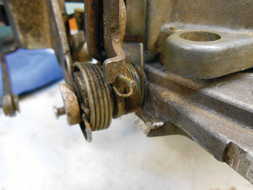
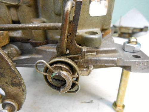

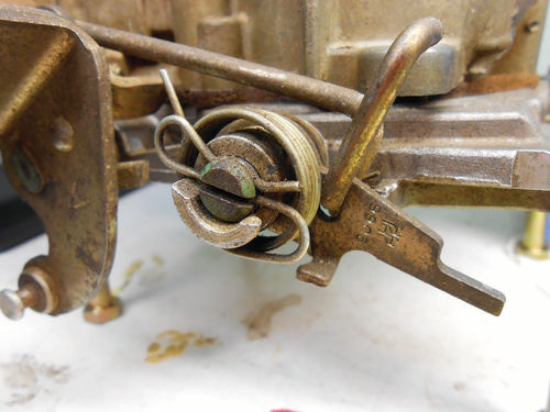
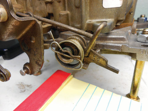
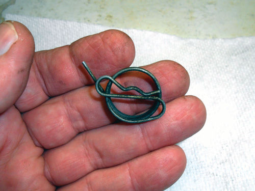
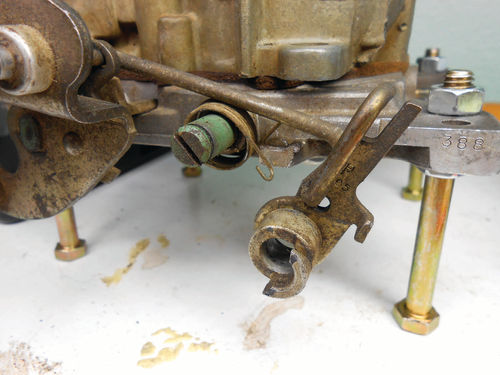
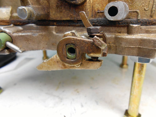
With all still elevated on the bolts, now is a good time to disconnect the linkage so that the throttle shafts can be removed. Photo 61 shows there is linkage connecting the primary and secondary throttle shafts that will need to be disconnected. Start by unloading the pressure from the inner spring on the secondary shaft. Photo 62 shows it unloaded. The pressure is off, and the tip is straight up in the air. As seen in this photo it would be rotated counterclockwise ¾ of turn and the tip lifted up onto the protruding aluminum tab to reload the spring. Photo 63 focuses on the secondary shaft’s outer spring, what I refer to as the “hitch pin spring” due to its shape. Photo 64 shows it’s now unloaded. This spring rotates clockwise and is positioned under the lever’s ear as seen in the previous photo. Opening the primary throttle shaft will push the lever on the secondary shaft back, as seen in Photo 65. Lifting up on the top of the spring’s clip will lift it out of the shaft groove as shown in Photo 66 (excuse my note pad). Photo 67 shows what this spring looks like, and with it off there’s no longer anything retaining the lever.

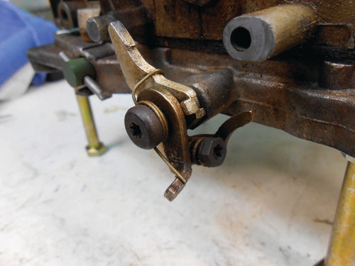
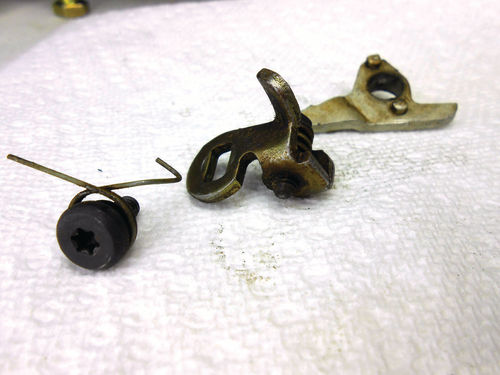
With a hard pull the lever slides off, the inner spring is visible and ready to slide off as well in Photo 68. If the lever is stubborn and won’t quite slip off, wait until either pair of throttle valves have been removed and slide that shaft out slightly. This will allow it to slide off easily. While it’s not absolutely necessary, a few twists and turns with that secondary lever gets it out of the way here in Photo 69. Now to the other side, Photo 70 shows the fast idle cam follower (pointing up) and fast idle adjuster that need to be removed. Unload the spring tension, and then with a T-20 driver, loosen and remove the screw and spring. Photo 71 shows all that’s remaining is to pull the adjuster and follower straight off. Photo 72 shows the removed screw, spring, adjuster, and fast idle cam follower.
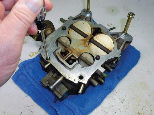
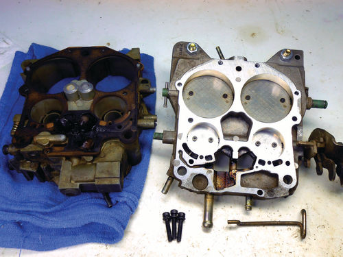
I chose to leave the fuel bowl on the throttle body, but once all the parts had been removed from the bowl, it could have been separated at any time. So as you see in Photo 73, a T-25 driver is used to remove the three retaining bolts. Once separated, Photo 74 shows the bottom of the fuel bowl with gasket and top side of the throttle body. At this time the two “stand” bolts at the rear of the throttle body are removed and replaced facing upward, and the two bolts with the taped ends will be inserted up front facing the same way when needed.
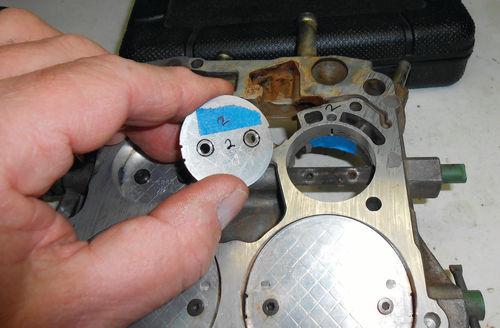
This positions it bottom side up for our next step. Photo 75 shows the bottom of one of the primary valves that will be removed. The protruding screw threads are distorted to avoid them from vibrating loose. Before continuing, references marks are lightly scribed along both sides of the throttle shaft on the bottom side of the primary valves as seen in Photo 76. On the opposite side of the valves the perimeter of the screw heads are also marked. These references will make proper alignment of the valves easier when the time comes. Also each valve is marked to identify it with its specific bore, and forward orientation in the bore.
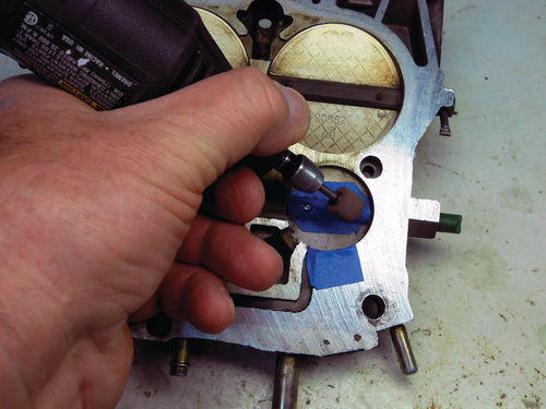
A Sharpie was used to mark the throttle valves, but it wiped off much too easily. Instead a small piece of masking tape was applied to the valves, and it was marked with the Sharpie. This was much better. Besides, should the tape start to come loose, it would be quickly noticed. Those protruding screw threads must be ground flush to the shaft for removal. A Dremel tool is an excellent choice, but an air grinding tool also can be used. Regardless, a small stone is essential to work with. It is unlikely to grind off these threads without accidentally leaving some minor marks from the stone on the throttle shaft. In an attempt to help reduce the number of undesired marks, masking tape was used to protect the shaft. In Photo 77 a coarse drum style stone 7 ⁄16" in diameter is being used to initially grind down the threads. Once close to the shaft, a fine cone-shaped stone was used to finish the grinding.
With all the threads on the primary shaft ground flush, the screws are now ready to be removed. The screws require a T-8 bit—be cautious not to apply too much pressure or you risk twisting off the heads. Yes, they will definitely be tight, but use common sense. If they loosen slightly and then bind, double check to make certain the threads are ground flush to the shaft. Penetrating oil is always an easy option to add to the mix, and if necessary apply some heat to that area of the shaft with a propane torch. Just heat it for 5 to 10 seconds and try removing the screw again.
The first two screws removed without any difficulty, and Photo 78 shows the throttle valve lifted out. Photo 79 shows a couple of minor grinding stone marks alongside each threaded hole. As a comparison, the threads on the second primary valve were ground without any masking tape protection. It actually turned out slightly better. Evidently without the tape the visibility was better, and so was my aim. Well, it was worth a try.

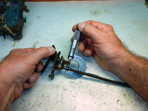
The second valve was also removed without any problem, and the shaft was slid out as shown in Photo 80. The shaft appears to show only very minimal wear, and checking it in several locations with a micrometer as seen in Photo 81 confirms it. There was no more than .001” undersize in the wear areas, so this confirms that the throttle body is in need of bushings. That green coloring you may have noticed on the throttle shaft is actually an anti-wear coating applied by the manufacturer, so do not try and remove it. Cleaners are fine, but don’t take it over to the wire wheel or abrasive blasting cabinet for cleaning.
Next it’s time to remove the secondary throttle valves so that they too can be repaired. The procedure is the same as with the primary side except you will have more working room when grinding off the screw threads due to the very large throttle valves. Remember to scribe each valve to reference its proper orientation to the throttle shaft as well as screw heads. Also identify each valve with the bore it came out of, and which end faces forward. Once the valves are both removed, slide the throttle shaft out, although it will remove from the opposite side. Inspect the shaft just to be certain it is in good shape, and then the throttle body is ready to be fitted with its bushings.
With all that grinding, abrasive grit and dust are everywhere and should be thoroughly washed off. They can dull and shorten the life of the cutting tools that will be used in the repair, and naturally you don’t want any trapped in the throttle body where it eventually would end up inside the engine. But before doing that, there is still one more task that the grinder will be used for.
Next, we’ll turn to the idle mixture screws.


