
Milt’s Tune-Up Advice
He Quickly Found One Problem With This Fuel-Injected Engine. Too Bad They Weren’t All That Easy to Diagnose.
WOW, THE FIRST big thing wrong with this ’92 Ford pickup equipped with a 4.0-liter V-6 port fuel injection engine and a mass air flow sensor was pretty obvious.
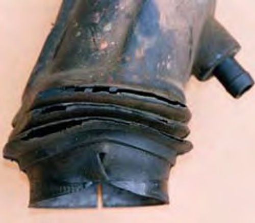
The air inlet duct from the air filter (Mass Air Flow Sensor location) to the throttle body was rotten on the underside. It had large cracks and holes allowing “false” air to enter the induction system without being measured by the MAF (Mass Air Flow) sensor. See Photos 1 and 2.
The tune-up symptoms (complaints) included rough running, surging idle, backfire, overheating (boiling over after engine shutdown), and “many codes” displayed on a “code reader.”
The engine and transmission had been rebuilt. A new radiator and thermostat were installed. An electric fan with its own shroud was installed. “It still overheated,” said the owner.
Tune-up Approach
How about just “fixin’” the “inlet tube” and start it up? Nope! There’s lots more to complete the tune-up, and perhaps some computer wiring maintenance as well.
The tune-up included cranking system tests, inspecting the spark plugs, testing the PCV (Positive Crankcase Ventilation), measuring the manifold vacuum and fuel pressure measurements, cleaning the throttle body, cleaning the injectors, and then testing the computer system (codes and sensor values including the oxygen sensors).
Cranking Tests
Hook up a voltmeter across the battery, (+) to (-). Install a vacuum gauge at the “vacuum tree.”
Disable the ignition system so the engine will not start. This can be accomplished by disconnecting the primary plug at the coil pack. Be careful, the connector lock may break upon removal. If this happens, install a plastic tie strap when reconnecting.
Crank the engine for 10 seconds. The cranking voltage should hold above 10 volts while cranking.
Our case history truck cranked at 10.8 volts, and the battery voltage was 12.4 after cranking.
Next connect the digital voltmeter from the battery ground terminal to an engine ground. Crank the engine for 5 seconds. The battery ground voltage must be less than 0.2 volts. Our truck battery ground circuit measured 0.15 volts during cranking.
The starter sounded energetic, like it wanted to start.
All these cranking tests proved we had a good battery, starter and ground on our case history vehicle.
If your battery does not hold the voltage during cranking and it sounds like it will “run down during the cranking tests,” install a new battery.
Engine Tests
Next, watch the manifold vacuum while cranking. On a good V-6 engine you should measure at least 2 inches during cranking. Our V-6 truck engine measured 2.5 inches while cranking.
The “cranking rhythm” sounded smooth, indicating the compression pressure in each cylinder is equal.
Ignition System
The spark plugs in this case history engine are Bosch platinum, HR8DPXD, gapped at 0.055. The specification is Motorcraft AWS-F42C gapped at 0.052- 0.056 inch. All the spark plugs were tanorange on the inner porcelain. The normal color on a well-tuned computer controlled engine is white. I recommended installing the specified plugs. However, we’ll double-check the spark plug firing voltage after startup.
Ignition Misfire Checks: This vehicle is equipped with a distributorless ignition with a “brick” coil pack and an RPM sensor on the crankshaft dampener.
There was no ignition misfire using a Snap On kilovolt tester. The plug firing voltage measured from 10 to 15 kilovolts at idle increasing up to 25 kV when tromping on the throttle. This is normal and there were no “open circuit” plug wires.
Kilovolt testers: A kilovolt tester measures “peak spark plug firing voltage.” If plug wires are open, the kilovolt reading will be as high as 50 kilovolts (50,000 volts).
Kilovolt testers can be purchased through auto parts stores. One source is a SmarTach+ meter manufactured by General Technologies Corp. in Canada. It can be purchased through CarQuest auto parts stores, part #XSHATA100.
Induction System
This vehicle is equipped with a MAF (Mass Air Flow) sensor located on the air filter outlet. The air duct tube looked OK on the topside from the air filter to the throttle body. Upon removal of the air duct, however, we saw that the bottom side was “in shreds.” These major leaks cause lean air-fuel mixtures.
The throttle body was very dirty and “gummy.” It was cleaned with solvent (paint thinner) in the area where the throttle blade was touching the throttle bore.
Fuel Pressure
Fuel Pressure, Engine Off: The fuel pressure gauge (Sears) was connected (using the Ford adapter) to the fuel pressure 1/8 Schrader connection on the fuel rail. With the key on, engine off, the fuel pressure measured 42 PSI. The specification range is 35 to 45 PSI.
Fuel Pressure, Running: The fuel pressure measured 35 PSI at idle and increased up to 44 PSI upon “tromping” on the throttle.
The fuel flow measured around 200cc into a plastic jar in 10 seconds.
The fuel system performance is all OK and it looked like the fuel filter had been changed. It is located on the left frame rail.
Engine Tests, Running
Manifold Vacuum, Running: The intake manifold vacuum measured 19 inches at idle, 21 inches at 2500 RPM in neutral (steady RPM), and 25 inches during a fast closing of the throttle (a quick “decel” condition).
All of this proves the engine is a good “pump” and the catalytic converters were not plugged.
Idle RPM Tests: All tune-up items were OK up to this point. However, the engine was still idling fast at around 1000 RPM. Pulling the shift lever into drive, the RPM dropped to around 800 RPM. Turning the wheels “loaded” the engine slightly. The idle RPM dropped off to around 750.
The idle control system was “holding the RPM” steady.
Computer Scanner Check
A Snap On MT2500 scanner was connected to the DLC (Diagnostic Link Connector, OBDI). The key on, engine off code check showed at least 6 code numbers all related to a lean air-fuel mixture on banks 1 and 2. (Note: Bank 1 on a Ford V-6 engine is cylinders 1, 2 and 3. Bank 2 is cylinders 4, 5 and 6.)
These “lean codes” are a result of the leaking air duct mentioned above and most likely was the major cause for the “lean codes” being stored.
The codes were “cleared” and the key on, engine run code tests were performed again.
The “lean codes” did not reappear in the key on, engine run or in subsequent key on, engine off tests. However, preexisting code numbers re-appeared showing transmission circuit problems.
Scan Data Stream
Coolant Sensor: After running for 15 minutes, the coolant temperature was measured at 85° C (around 180° F) at 0.6 volts on the “ECT” (Engine Coolant Temperature) scanner display.
This vehicle did not overheat during the tune-up after installing the new air inlet duct.
Oxygen Sensor: Both oxygen sensor voltages were varying from 100mv up to 800mv at every scanner “update” (around 1 second) on banks 1 and 2. This is normal.
IAC (Idle Air Control): This stayed constant at 31%. It did not vary when turning the front wheels to load the engine. However, the engine was still idling fast.
Fuel Trim: The fuel trim numbers for both banks 1 and 2 were initially +25%, but decreased down to around +10% as the engine was idling and being driven on the road.
These fuel trims (long & short term) indicated the computer system had been correcting rich for a very lean mixture. However, the decreasing fuel trim numbers indicated the new air duct was causing the computer to adjust back towards a normal fuel trim range (±5%).
Closed Loop: The computer was commanding closed loop.
Additional Engine Off Checks
Since the engine was still idling very fast (1000 RPM in N), we proceeded to check the “minimum” idle. The IAC (Idle Air Control) motor was disconnected (engine off). The engine was restarted and was idling at 800 in neutral, which was very fast. In this condition (IAC disconnected) the minimum idle is usually around 500 RPM.
Upon further inspection, we found the throttle blade had a “rubber” plug that was hard and leaking air. We removed this plug and installed a new one (dealer item).
This reduced the minimum idle from 800 to 700—still too fast. All this adds up to more possible air leaks in the engine’s induction system somewhere or possibly a leaking idle air control motor.
We are continuing to look for these leaks. In many cases upper intake manifold bolts become loose, caused by gasket collapse and/or the gasket sucking in at the edge.
In addition, always pinch all the vacuum lines, one at a time.
On the Road
The engine was running very well. Leaving the scanner hooked up, we drove the truck on the road.
Acceleration was “strong” with no hesitation. Cruise was smooth with no surging. The engine restarts within 2 seconds.
The fuel trim numbers reduced from +10% down to a normal range varying from -3 to +5%.
Computer System Maintenance
Up to this point, all the computer trouble codes were caused by a lack of maintenance and the leaking air duct. But we did find one computer system maintenance problem—the computer ground circuit at the fender well needed to be cleaned.
The computer ground at the throttle sensor position (backprobing) was reduced from 0.25 volts down to 0.12 volts after cleaning the ground connection on the fender well.
This cleaning of the computer ground also reduced the throttle position sensor (TPS) reference voltage from 5.30 down to 5.07 volt. The throttle position sensor signal voltage was reduced to 0.88 down from 1.09 just by cleaning the computer ground connection on the fender well.
All of these abnormal computer system voltages were caused by a poor computer ground, a rusty connection on the fender well. This is a lack of maintenance problem, not a computer problem. Also recall that the leaking air duct had been causing all the “lean” codes.
Results & Recommendations
The truck did not overheat, running at 88° C (190° F) during the road test.
During the road test the transmission codes “reset.” I recommended the transmission computer circuits be rechecked at the transmission shop.
The owner is still concerned about overheating. However, the engine is not losing coolant. I recommended replacing the electric fan with an OEM clutch fan and the fan shroud.
In addition, the owner is checking the upper intake manifold for vacuum leaks. Remember, the minimum idle is still up around 700 RPM in neutral.
Resource
“Tuning Up Autos and Trucks—A Guidebook of Solutions for Testing, Evaluating, and Analyzing Computer Controlled Vehicles” By Milt Webb www.milttheinstructor.com


