Diagnosing and Replacing an A/C Compressor Clutch Part 2
After Completing a Practice Round, It Was Time to Fix the Car’s Compressor. It Worked Fine for a Year and Then…
Editor’s note: Last month when the A/C in the author’s 1986 Caprice started to pump out warm, humid air he did some troubleshooting and determined that the unit needed a new compressor clutch. He then started a practice run with an old “test” compressor. He’ll wrap that up this month and turn his attention to his car’s compressor. There were 18 images in the first installment so we’ll pick up here with Photo 19.
Reassembling the Practice Unit
With the old clutch and coil off, do any clean-up if necessary and it’s time to reassemble. This being just a practice run, the old clutch will be going back on. While not called for, I prefer to use a very small amount of grease on the compressor nose and the inside bearing race.
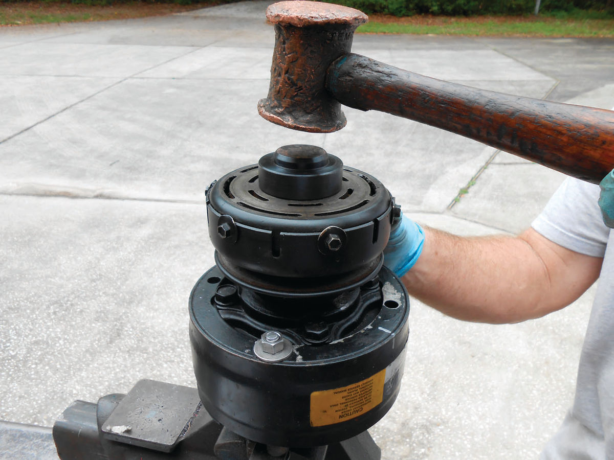
Initially the rotor and coil assembly fits loosely over the compressor nose. Gently press down on the rotor while wobbling it slightly back and forth to get the bearing started. Use the correct-size bushing and soft face hammer to drive on the rotor as shown in Photo 19. This bushing drives against both the inner bearing race and rotor face. Once started, verify the terminal positioning is correct, and that the locator bosses on the coil are lined up properly with the wells in the compressor as shown in Photo 20.
Continue to drive the assembly on until the coil is firmly seated and then replace the snap ring (beveled side facing out).
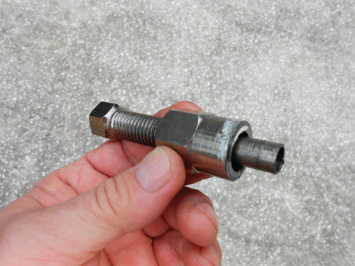
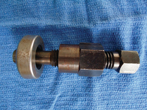
The drive plate is next. The installer you see in Photo 21 will be threaded onto the shaft of the compressor and the large nut is tightened against the drive plate. With this setup you end up holding the nut while rotating the center screw counterclockwise, and this will pull on the drive plate as is being done in Photo 22. After several rotations it’s a good idea to loosen the large nut and thread in the center screw, as this style tool does unthread itself from the shaft as the drive plate is being pulled on. So repeat as necessary. The deluxe version of this tool is shown in Photo 23 and utilizes a bearing between the large nut and drive plate. If using this tool it’s mounted the same but you rotate the large nut clockwise while holding the center screw. With this design the center screw won’t thread its way off, so it’s a little faster but both work fine.
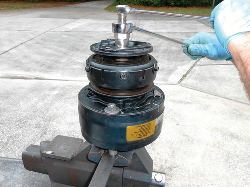
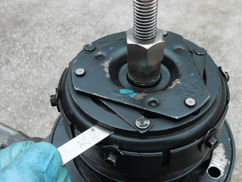
Once the drive plate gets close to the rotor, it’s time to start checking the gap using a feeler gauge as seen in Photo 24. The service manual specification is .020”-.040”. Check it in several positions as it is unlikely to be identical at each point. Essentially you average it out. You have a large tolerance to work within so as long as the tool is tightened in small increments there should be no problem. When you think it is correct, loosen the tool’s nut and recheck. Should you accidentally tighten it too far, you will need to remove this tool, and replace it with the removal tool. It certainly isn’t the end of the world, but if you work slowly you can avoid it.
With the clutch air gap set, the nut is replaced and torqued to 10 ft.-lb. Recheck the air gap one last time and this job is now complete. Performing the job on the vehicle is a bit more difficult mainly due to obstacles, but on the plus side, it can be done without becoming involved with the refrigerant side of the equation. The system retains its full charge, so that is a huge timesaver, and eliminates the need for more tools, refrigerant and equipment. This is also the benefit of just replacing a bad clutch in lieu of replacing the entire compressor and clutch.
Moving On to the Car’s Compressor
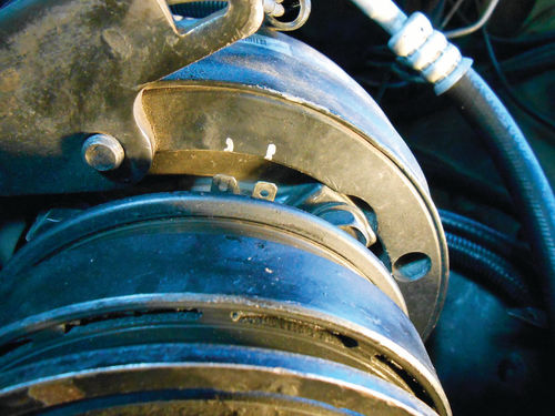
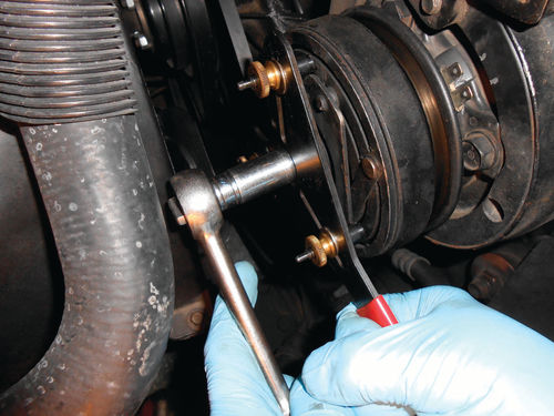
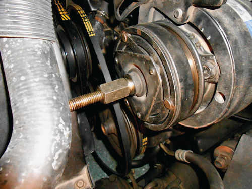
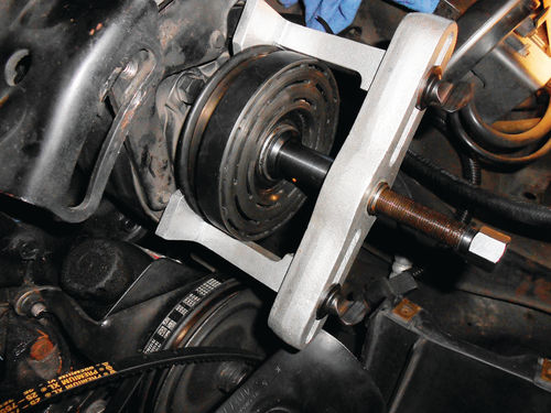
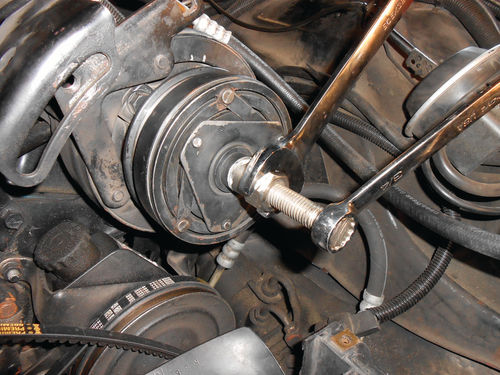
Start by removing the compressor’s three slide adjustment bolts and loosen the lower pivot bolt. A 15mm wrench is all that’s needed. Next remove the drive belt, and then swing the compressor out as far as it will go to yield some working room. Remove the electrical connection to the compressor and make a reference mark for the terminals as shown in Photo 25. The spanner tool is used to hold the drive plate while the nut is removed as seen in Photo 26. The same puller we used before is installed on the drive plate in Photo 27. You can see it is partially hidden by the upper radiator hose. The pressure screw is tightened and the drive plate removed without any problem. Notice also in the photos that this clutch is different. This is the sixpole clutch, also referred to as Frigidaire/ Harrison. Those six perimeter screws are missing for one thing, and notice its more linear appearance.
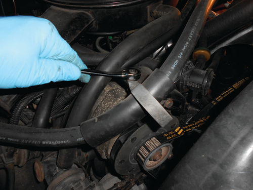
The working area was a bit too confined, so to allow more free movement of the compressor the A/C hose retaining loop was removed from the alternator bracket as seen in Photo 28. Then reluctantly some coolant was drained from the radiator; the upper hose pulled out of the way and the top half of the fan shroud removed. Now there was considerably more room to work, as well as take photos. While this is a little frustrating, the small amount of time spent to do this will make everything easier and save time in the long run.
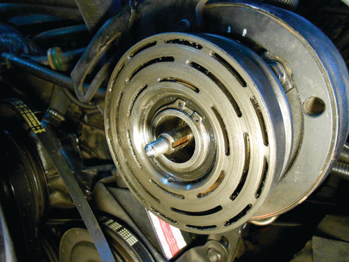
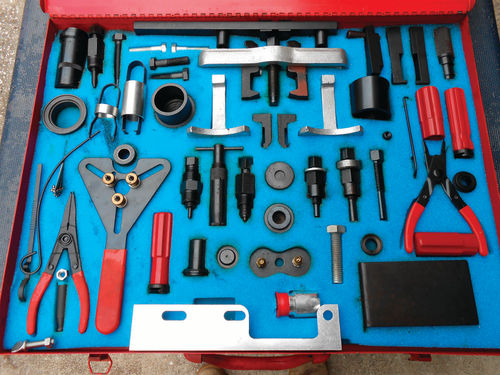
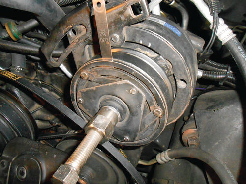
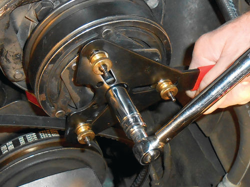
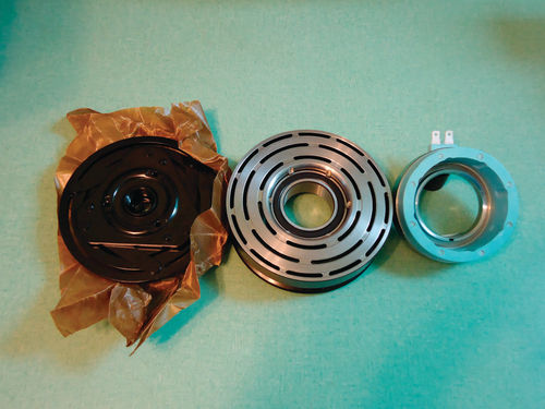
A look at the rotor in Photo 29 shows some other differences in this unit as well. While there is a snap ring retaining the rotor to the nose of the compressor, the bearing is almost flush with the face of the rotor. That groove on the inside of the four-pole rotor used for removal on the test compressor has no place to exist on this rotor. The puller configuration previously used is of no value here. Luckily that puller is part of a much larger collection of A/C tools (Photo 30) that includes many items I have never used, and likely never will. There were two large arms with curved jaws that fit the puller. They disperse the pulling pressure over a large area, avoiding any damage to the rotor or pulley as seen in Photo 31. Note in the Chevrolet service manual they show using a puller that locks into the slots in the face of the rotor. As stated earlier, don’t be alarmed if the specialty tools aren’t identical to the ones shown in this article. But do make sure they are correct for your application.
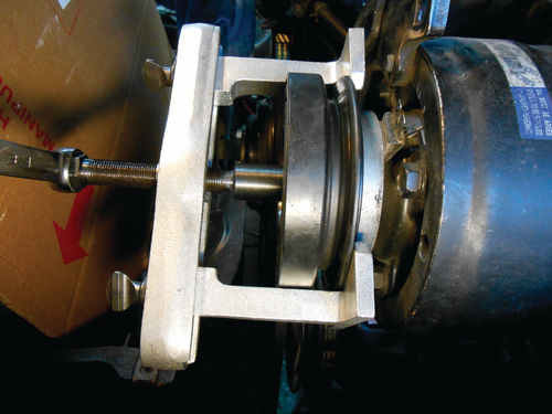
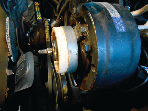
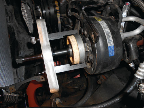
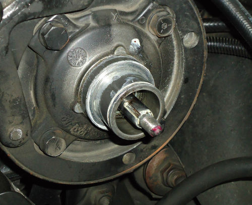
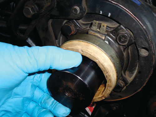
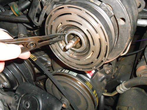
Photo 32 shows a couple of things. First a section of corrugated cardboard has been placed in front of the nowvulnerable radiator for protection. Second the rotor is being removed while the coil is remaining behind. The coil is also pressed onto the nose of the compressor as shown in Photo 33. None of the previous puller arms would fit the job, but there were still more to choose from as you can see in Photo 34. This coil has no locator bosses on the back. It’s smooth and is pressed onto that largerdiameter shoulder at the rear of the neck seen in Photo 35. Because of this the terminals can be located in any position, so pay attention when installing the new coil. Look closely at the photo and you may notice the “X” marking on the top front of the compressor. This agrees with the location marks made for this coil but it might not with other applications.
Plans were to install a good used four-pole clutch that I had on hand, but due to that raised shoulder that’s not possible. If you compare Photo 17 of the test compressor with Photo 35, the differences are easy to spot. I wasn’t aware of this when planning, so now I needed to purchase the correct clutch.
I looked on www.rockauto.com, a site that I often visit for components, and this six-pole clutch wasn’t listed for a 1986 Caprice, so I decided to check the listing for our 1987 El Camino and there it was. Similar situations have been encountered in the past, so it never hurts to crosscheck listings on items that are known (or believed) to be interchangeable. Also a remanufactured coil-only was listed as well.
There were no plans to leave the vehicle apart for any length of time as it’s our daily driver. At best it would be a couple of days before the new parts would be in hand, so a change of plan might be in order. As it turned out there was quite a bit of oily dirt built up in front of the coil, inside the rotor. Is it possible this had an effect on the clutch performance?
In an effort to make certain the clutch malfunction wasn’t caused by dirt or oil on the friction surfaces, both the rotor and drive plate were cleaned as best as possible before disassembly, and the A/C Clutch was rechecked, but there was no change. This area inside the rotor however was not accessible until all was disassembled. I decided to perform a couple of simple ohm meter tests of this questionable coil. First was to check each terminal against the coil frame for a possible ground; none was indicated. Next was to take a resistance reading across the two terminals. As it turned out it read the same as the one I had planned to replace it with. There are no ohm values shown for the coil in the service manual, so this is just a comparison between a questionable coil and a known good one. Naturally the coil might perform differently under the hood at normal engine operating temperature, and the only way to test that was to put it all back together. Generally I wouldn’t consider doing this, but in this situation it gets the Caprice back on the road. The worst case scenario would be that the A/C performs as it did previously and the clutch will have to be removed again but we’ll have use of the vehicle until we get the parts. The other possibility is that the A/C works perfectly, the expense of the new clutch will be saved and the job is complete.
Some might question where that oil originated inside of the rotor. The previous year quite a bit of engine work was done on the vehicle and during that time the compressor was removed from its mounting brackets. The system remained fully charged and the compressor was supported to avoid any stress on the hoses. It was, however, tilted in an abnormal position and remained that way for an extended period of time. During that down time I suspect some refrigerant oil leaked past the shaft seal and accumulated inside the back of the clutch rotor. Had there been any refrigerant leakage, it was minimal, and the system required no additional charge.
You might think if oil escaped, then certainly so did a good amount of refrigerant, but it doesn’t necessarily work that way. Back in the late 1970s GM encountered an abnormally high number of A/C evaporators that had developed leaks. One of the major reasons evaporators fail is due to moisture trapped in the system. At least back in the days of R-12 moisture trapped in the system combined with the refrigerant and created an acid that would corrode the evaporators from the inside out. At that time GM was using a small-diameter braded nylon high-pressure A/C hose. They discovered that the construction of the hose allowed moisture to somehow pass through it and enter the system, however no refrigerant escaped. It seems hard to imagine, but it happened. Those hoses were ultimately replaced with the more typical rubber hose and the problems ceased.
Back to the present…the shaft seal had never slung oil prior to the clutch service so all things considered the decision was made to thoroughly clean the old clutch and reinstall it. Let me stress that I wouldn’t recommend doing this normally. If the new parts were right at hand, they would be installed without question. If I were working in a shop on someone else’s vehicle, it wouldn’t even be considered.
Putting Things Back Together
First a minimal coating of grease is applied to the neck to aid installation of both the coil and rotor. The coil is slipped back onto the nose of the compressor with its terminals properly oriented. This will be driven on just as was done with the compressor on the bench using the proper-size driver bushing as seen in Photo 36. The bushing must be deep enough to avoid contact with the end of the compressor shaft or damage may occur. Actually what is shown in Photo 36 is a combination of two special drive bushings. The long one is visible, and beneath it is a mating short bushing to yield the needed depth. The slide adjustment bolts that had been removed to allow greater access were replaced in order to have a solid mounting to drive against. Once the coil is completely seated, the rotor follows. It is installed in the same manner but the drive bushing was slightly different. Both the coil and rotor are driven on until they bottom out. This almost seems primitive, but it is the proper method. A worthwhile tip is to take some measurements for future reference between the back of the rotor and face on the compressor prior to removing the clutch. Pick one reference point and use it for both the rotor and coil (once the rotor is removed). Drill bits are handy for gauging distance. I found myself questioning if the coil was actually fully seated because there was a visible gap on the shoulder behind the coil. Well there should be, but my uncertainty had me remove the coil once for inspection. You may be able to feel when the coil has bottomed but not always and you certainly don’t want to beat on it any more than necessary. Should one of these six-pole clutches be encountered again, I won’t forget there is a shoulder and that there should be a slight gap behind the coil.
With the rotor fully seated, Photo 37 shows securing it with the snap ring with the beveled side facing out. The drive plate is lined up with the keyway and the same installation tool used on the test compressor clutch is used in Photo 38 to pull the drive plate on. In Photo 39 a feeler gauge is used to establish the .020”-.040” air gap as was done with the test compressor in Photo 24. Check it in several locations as there usually will be some variation. Once satisfied, remove the installation tool and recheck it.
The last step is to replace the nut on the front of the shaft as shown in Photo 40. The spanner holds the drive plate while a torque wrench is used to apply 10 ft.-lb. of torque. Rechecking the drive plate air gap once again isn’t a bad idea.
Now the coil plug can be reconnected, the bolts loosened so that the belt can be replaced and then tightened. All that remains is to test it.
Initially all looks good. I started the vehicle, turned on the A/C and set the fan to the lowest speed. This will make the clutch cycle on and off the most. If it were still going to act up, this should do it, but there were no problems.
The next day we took it for a normal drive into town. There were many stops where the vehicle was shut off for a while and upon restart all performed as it should. If in a week all is normal, then this job is done. Should it need to be revisited, there will be no surprises. Now it all seems very familiar, so a repeat performance wouldn’t take much time at all.
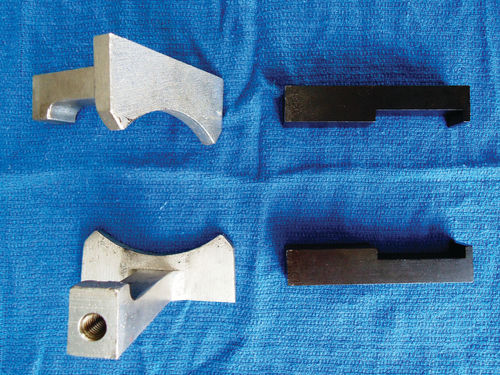
Overall the replacement of either clutch is actually quite straightforward with nothing complicated or confusing. Photo 41 shows a close view of the puller arms used in conjunction with the puller frame for the six-pole rotor and coil. Having a service manual to reference is essential, especially if your vehicle’s compressor is different from what was covered here. Having the proper tools is essential to a successful job. If you don’t have them, make sure they can be rented or borrowed. Hopefully seeing some of the tools used here will give you a good idea of what you will need to perform the job successfully and decide if it’s a task you want to tackle.
Well, It Worked Great But Then…
It was close to a year since the completion of the A/C Clutch service, and it had been working flawlessly, but suddenly the same problem occurred. Coincidentally I had just been talking with a friend about this A/C experience, so that likely jinxed it.
A new clutch was purchased (Photo 42) and installed without any difficulty.


