
How -to Rebuilding a Starter, Pt.3
It’s Time to Replace Bushings; Reassemble and Test the Unit. Now, Why Isn’t It Spinning the Way It Should?
In the first two installments in this series we disassembled the unit,ran tests and started the replacement of some “normal wear” items. In this final installment we’ll replace the bushings and then reassemble and bench test the starter. There were 26 images in the first two installments, so we’ll resume here with Photo 27.
Replacing the Bushings
There is a special puller for removing these bushings, but I don’t own that neat little tool, so my approach is to pry the bushings out.
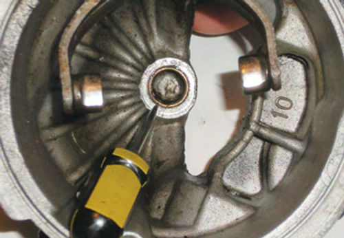
The Rear Bushing: Due to the thin wall thickness of the bushing (.047”), and the fact that the bushing is relatively soft, I decided to use a small, straight pick tool and a hammer to perform the task. (I would avoid using a chisel to remove the bushings, as there is a much greater chance of doing damage to the surrounding area.)
Start by catching the edge of the bushing with the pick tool, as seen in Photo 27, and tapping it lightly with a hammer. The leading edge of the bushing will cave in and tear very easily.
Once started, straighten the angle of the pick tool so that it is more in line with the bushing. The idea is to force the pick in between the bushing and the wall in the rear cover.
Proceed by tapping the pick tool in deeper, then push inward, toward the center of the bushing, and the bushing will tear. This process is repeated until the bottom has been reached.
Once the bushing is split open from top to bottom, it’s easy to lift out, as there is no longer any retention. The removal only took a minute or two.
Grease and debris remained in the well for the bushing, so I thoroughly cleaned it and used a Dremel tool and stone to smooth out several burrs and rough spots. A light coating of petroleum jelly was applied to both the inside of the well and the new bushing in preparation for installation.
You can use any number of methods to install the bushing, a bench vise, press, large C-clamp, or even a drill press. (While it’s certainly not out of the question, I prefer to not drive the bushings in with a hammer, because you would be more likely to damage the new bushing.)

I chose the drill press because its table allowed the “well” of the rear cover the clearance needed to lay flat (Photo 28).
With the bushing squared up, and a block of wood between it and the chuck, I pulled down on the drill press feed, pressing the bushing home. Pay attention to not set the bushing any deeper than it was originally. Test fit the armature in the rear bushing; it should turn easily. If it doesn’t, check the new bushing for possible damage or debris and try again. If there is minor damage to the edge of the new bushing, you can usually clean it up carefully with a file. A snug fit is good…tight is not.
The Front Bushing: The bushing in the pinion housing is the one that wears the most. Before getting involved, take a moment to inspect the shift lever and its pivot pin (or bolt) for any abnormal wear or looseness. This typically isn’t a problem; but if you don’t check it, it surely will be.
Replacing this bushing is virtually the same as with the rear, only the work area is more confined. Due to the pinion housing’s limited access, I entered the housing with the pick tool as though it were the armature, as seen in Photo 29, and proceeded as we did with the rear cover bushing.
Note: Your pick tool must have a sharp point to get it started; if not, sharpen it lightly with a grinding stone. As before, continue to tap the pick in, and then push it in toward the bushing’s center to tear it. Once complete, simply lift out the old bushing. The new bushing is replaced in the same manner, only this time you must be more vigilant that the bushing and pinion housing are properly lined up. The pinion housing’s nose will fit into the hole of the drill press table, but instead of lying flat, and sitting square, it can be at most any angle. The same block of wood is used again, but this time it’s used lengthwise. Its length is used as an extension for the drill press chuck to reach the bushing. If the bushing doesn’t start to press in with gentle pressure, verify that it’s properly lined up before applying more force. Finally, test fit the armature again, as we did with the rear bushing.
An Important Tip: Don’t decide to skip the replacement of the bushings. It’s not difficult, doesn’t take long, and leaving a worn-out bushing in the starter can make all of your previous work “wasted effort.”
Time to Reassemble the Starter
Begin the unit reassembly by putting a tiny amount of grease inside of each bushing and spreading it around. (A toothpick or Q-tip will do a good job.) Don’t apply any grease to either of the corresponding bushing surfaces of the armature. If you do, it will likely end up on places where you don’t want it, like the brushes, for example.
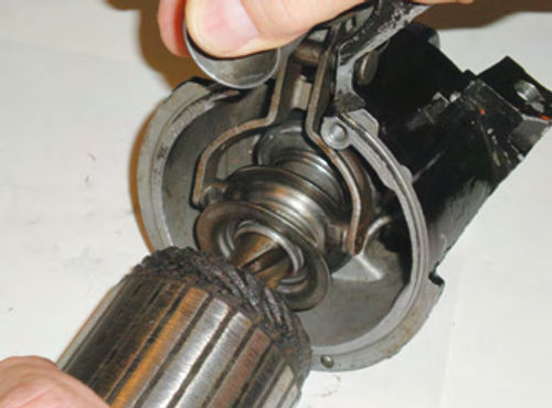
While holding the solenoid plunger forward, insert the armature and starter drive into the pinion housing, entering at an upward angle from below the shift lever as seen in Photo 30.
Once the shift lever ears are engaged with the starter drive, guide the armature into the front bushing. Make sure that the thrust washer is on there. The armature should rotate easily.
Next, stand the pinion housing with its nose down. The armature will now best and ing vertically. Carefully slide the field housing down over the armature until it stops.
You will notice the brushes have stopped the armature from going in all the way. By alternately spreading the brushes open, you will be able to move the edge of one brush, and then another, until finally all are up and resting on the commutator. By assembling the starter in this position, gravity will be working with you like an extra set of hands, pulling the field housing downward.
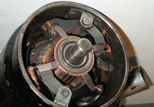
Photo 31 shows the brushes in their proper position with relation to the commutator. They should all be lying flat, making full (or virtually full) contact against the commutator.
If the field housing hasn’t seated snugly, twist it back and forth until the alignment pin finds its proper location in the pinion housing. Now place the leather brake washer onto the rear of the armature, and put on the rear cover. Line up the marks made earlier on the plate and housing (take another look at Photo 5 in the December issue), then thread in the two long through bolts. Don’t be surprised, as there usually is still a bit of “fishing” to get the threads started. Once the bolts are started, snug them down. I didn’t locate a torque specification for these bolts, but 5 foot-pounds would seem to be more than adequate.
Finally,it’s time for the solenoid.There are no tricks here; it goes back on in the reverse order of its removal. Replace the large return spring over the solenoid plunger and then slide it into the solenoid. Push the solenoid straight forward against the spring’s pressure, turning it as needed until it can drop down in front of the flatfield terminal. Now rotate it until its “tang” secures in between the two housings. Once the holes are all lined up, loosely start all the screws, then tighten them down. With that, the rebuild and reassembly are complete.
There will be parts remaining in the Victory Lap rebuild kit, because it covers several applications. For example, an extra bushing and a set of smaller brushes were left over after finishing this starter. I can’t throw things like that away, asI might find a use for something later, so it all goes into a “junk” drawer. Even the old snap ring and collars that were replaced with new ones are saved. You can develop your own “Award Winning Parts Department”…just come up with a method to keep track of what you have and don’t let it get out of control.
Bench Test the Starter
It’s always a good idea to do a bench test prior to the installation of the rebuilt starter. There shouldn’t be any problems, but if there are, now is the best time to find out.
The starter can simply be tested to see that it spins, sounds good, and the drive engages, or a “no-load” current draw test can be performed, and checked against specifications.
Both will require the use of either a 12-volt battery or a high-output battery charger with a “Boost” setting.
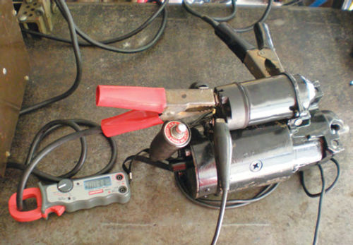
If a battery is used, battery cables also will be required, or a set of jumper cables can be substituted if they’re used carefully. In addition, using a remote starter switch is a good idea. Photo 32 shows the starter connected and ready for testing. The connections are as follows:
TheRedClamp (or battery positive)is supplying the positive connection to the battery terminal of the solenoid, and it has an induction amp meter clamped over its cable.
The Black Clamp (or battery negative) is the ground connection, and it is connected to the ear of the solenoid and drive housing (any bare metal surface will work).
The Remote Starter Button has one clip connected onto the red clamp (solenoid battery terminal), and the other to the “S” terminal of the solenoid.
It’s a good idea to secure the starter to the work bench with a clamp for a little extra security, and if you are working on a steel-topped workbench as I am here, be aware that it’s most certainly conductive. For safety, a piece of cardboard or wood can be used over the top of the bench to avoid any accidental welding.
What Went Wrong?
With the battery charger on and set to the “Boost” mode, a press of the remote starter button is all that should be needed to bring the starter to life… But to my surprise, the starter hardly rotated at all.
This starter had always spun over well before the overhaul, so what had been changed that was causing this new problem? Maybe I missed something. I reopened the starter and rechecked the new bushings for excessive drag. The fit was fine. Certainly the brushes were all laying flat on the commutator, but another look never hurts. Once again, all looked fine
Then I noticed the new leather braking washer. It seemed considerably thicker than the old one it had replaced. Could it be that this washer was binding up the starter? I reassembled the starter, only this time with the old worn leather braking washer. Now the starter performed as it should; problem found.
This shows the importance of never disposing of any old parts until the job is completely finished. To solve the problem I decided to reduce the thickness of this washer using my bench-mounted bent sander. Carefully running the coarse sanding belt against the rough-cut side of the leather washer did the job.
There may be a better way, but this worked, and ultimately took care of the problem. Finally, I applied some graphite to both sides of the leather washer.
During the current draw test a reading of 70 amps was initially obtained at start-up and, once it was running for a few seconds, it fell to 60 amps. The specs in my shop manual are 49-87 amps,so all looks good.
Some Requirements May Vary
If the vehicle you’re working on doesn’t have a Delco starter, then use the information in this article as a guide. While parts replacement will vary, you will still perform the same tests, and be working with the same components. Armature testing will be the same, and while field coils will still be checked for open or grounded conditions, the test connections may be different. Refer to your vehicle’s shop manual to verify the unit’s disassembly and testing procedures. If you choose to use one of the Victory Lap Starter Kits, as I did, it includes basic instructions on parts replacement for each application.
All that remains is to put the starter back on the vehicle.
On my ’66, the inspection cover must be replaced before the starter, so keep that in mind as your vehicle might require the same process.
Once installed, I noticed that the starter was operating more quietly than before. It used to function with a slight clunk that was now gone. This was most likely due to the worn-out leather braking washer that was replaced.
Now it’s time to enjoy years of trouble free starter service…and turn to another automotive project.
Resource
CPI Divisions
PO Box 678, West Concord, MN 55985
cpidivisions.com Victory Lap rebuild kits


