
How -to Rebuilding a Starter, Pt. 2
We Still Have a Few Tests to Perform on Our Disassembled Unit. Then We’ll Start to Replace Some Worn Parts.
LAST MONTH WE began our starter rebuild by disassembling the unit andrunningsometests.We’ll resume the testing here and then get into the replacement of some“normal wear”items. There Were 14 images with the first installment, so we’ll start here with Photo 15.
Testing for an Unwanted Ground
Simply move the test lead from the insulated brush to the grounded brush while keeping the other test lead connected to the flat field terminal as seen in Photo 15. Make sure the insulated and grounded brushes don’t touch each other, or you will obtain a false reading. The growler light should remain off, and if testing with a voltmeter, there should be no reading.
Go a step further, and with both test leads still connected, use a hammer and lightly tap on the outside of the field housing, usually in the area where you see the countersunk bolts that retain the pole shoes is a good choice. Is there any change? If the light comes on, or a meter reading is obtained, the field coils are grounding somewhere. You can even repeat this test by gently tapping on the inside of the pole shoes. If the indication is that they are grounding, they will have to be removed for further inspection, and possible replacement.
Removing the Field Coils
If the field coils require removal from the field housing, using a hand impact tool is one of the best choices. Photo 16 shows the tool, and one of the four countersunk pole shoe bolts that would need to be removed. This tool is a Craftsman, purchased decades ago from Sears, but you can find them through other hardware outlets. Included with it were two straight blade, and two Phillips bits. Other configurations can be purchased if the retaining bolts are something different. The bit holder can also be slid off, and you will have a 1/2-inch drive that you can put sockets onto.
To use the tool, first choose the bit that fits the bolt correctly. In this case it’s the #4 Phillips. Make certain to clean any grease, dirt or excess paint out of the end of the bolt head. These bolts are tight; you don’t want the bit to slip and damage them. It never hurts to use a little penetrating oil, and in this situation it can be applied sparingly both inside and out.

Note: Take a moment to reference the pole shoes to their locations, and the direction they are facing. Use a Sharpie marker, masking tape or something similar to reference each shoe to its particular location inside the field housing. It may or may not make a difference (depending on the starter), but it only takes a moment, and could save you a ton of time later.
Now, place the bit into the head of the bolt, and using your hand, twist the grip hard counterclockwise and hold it; then strike the end of the tool with a hammer. It may take two or three hammer strikes before it loosens to a point where it can be removed with a screwdriver.Replacement is accomplished in reverse order, and this time the tool would be twisted clockwise (for typical right-hand threads).
With the wires to the insulated brushes disconnected, and the pole shoes removed, push the flat field terminal in through the rubber grommet. Now the field coils can be slid out of the housing. If you remove the rubber grommet, you can safely clean the field housing in a parts washer, just be careful not to wash off or disturb any reference marks you’ve made for the pole shoes.
Some Possible Repairs
If the field coils indicated an open circuit during testing, inspect the coil to coil connections, and the wires that connect to the two insulated brushes. It’s possible that you may find a bad connection that’s loose and repairable.
If the field coils indicated they were grounded, inspect the insulation for cracks or worn covering that may have allowed contact to a pole shoe or the field housing itself. Evidence in the form of arcing marks would confirm the location.
If you can see the location where the ground occurred, it may be possible to salvage the original field coils. Clearthe insulation away sufficiently to allow a good view of the copper winding. If all looks OK, consider re-insulating with the appropriate material.
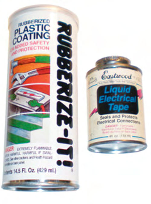
A plastic covering was used on the field coils in our subject starter, so had they needed insulation repair; I would have used one of the plastic coating products shown in Photo 17. The large can is a product typically used for insulating tool handles either by dipping or brushing. The other is liquid electrical tape, and it has a brush applicator inside the can’s lid. I would probably make the plastic coating my first choice, because it’s a little thicker, and it doesn’t seem to shrink, or at least not as much as liquid electrical tape. While the liquid electrical tape was purchased from Eastwood, both items should be available at your local hardware store.
If you are dealing with field coils wrapped in a fabric-type tape, again check the local hardware store. Bring the field coils with you to the store and get a knowledgeable clerk’s opinion on what might work. I suspect friction tape would be a good possibility, and my local Ace Hardware stocks it. When re-wrapping an area that had grounded, you must avoid making it too bulky. Overlap the existing insulation slightly, and maintain the same thickness. The pole shoes must bottom against the field housing when tightened, and the height of the coils must remain below the shoes.
My starter’s field coils were fine, and while you might consider removing them to do a complete cleaning inside the field housing, there is always the chance they could be damaged doing so. So, unless there were some other reason for removal, like visible cracking and peeling of the insulation, leave them in place. This starter is very clean inside, so I will simply use an old toothbrush to clean out any debris. If there were a buildup of oil and dirt, it would be carefully scraped out, and then a non-solvent solution, such as Dawn dishwashing soap and water, would be used to clean it up with the aid of a small brush. Once satisfactorily cleaned, rinse and then use low, regulated air pressure to remove any excess water. Set it out in the sun, and/or use a hair dryer to finish drying it.
Time to Start Replacing the Normal Wear Items

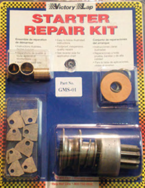
The replacement parts I have chosen all come from CPI Divisions, and are packaged in their “Victory Lap” starter repair kit, shown in Photo 18. It’s made in the USA and includes the brushes, starter drive, thrust collar, snap ring, retaining collar, braking washer and bushings, and it retails for about $20. They also offer similar kits for alternators, as well as hard-to-find alternator and starter parts. Their Website states: “We have the capability to locate and purchase virtually any component part that is associated with a starter or alternator. No matter how strange or rare the particular application might be.” They have been very helpful and a pleasure to deal with. For more information, contact CPI Divisions, PO Box 678, West Concord, MN 55985; visit their Web site at cpidivisions.com. They may be able to assist if you needany additional parts.
Replacing the Brushes
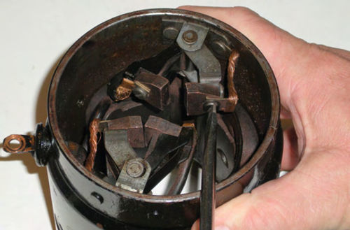
There are two approaches to replacing the brushes. With a long straight-blade screwdriver it’s possible to reach in at an angle, unscrew, and remove an old brush as shown in Photo 19. This is without question the quickest, simplest method, and in most cases, will get the job done.
But what if a screw is too tight or possibly a screw head is slightly damaged? In that case, you will need to remove the brush holders from their fixtures. It’s not particularly difficult, and it’s worth knowing what to expect, should the need arise.
The brush holders are retained with a pin that pushes in place. This is also visible in Photo 19 (as well as several earlier photos). Pull the pin straight up and out. The insulated brush holder sits inside the grounded holder, and will most likely stay together until you remove the spring clip. A little wiggling is all that’s needed to free the clip from the brush holders. Now rotate the holders to a comfortable position and, using a straight blade screwdriver, remove the old brushes. It’s a good idea to replace one pair, and then the other. This way you always have a pair to reference if you get confused.
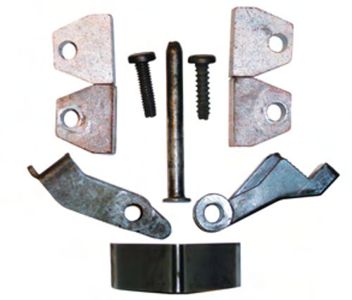
Photo 20 shows the components that have been removed. At the bottom is the spring clip, above and to the right is the insulated holder, while to the left is the grounded holder.
The spring clip fits into the recess of the insulated holder, and pushes against the back of the “brush stop” on the grounded holder. In the center of the photo is the pin that retains the holders. On either side are the brush screws. Note they are not the same. The metal holder uses a finer thread than the composite. At the top are the new brushes, while below them are the ones that were removed. They show virtually no wear, because they were replaced a couple of years ago.
When installing the new brushes keep in mind that they can be installed upside down.
When properly installed, the lower edges of each brush will touch (when they are pushed together), and there will be a 1/8-inch gap between the top edges as this close-up shows in Photo 21.
If they are installed upside down, the beveled faces will meet and make full face-to-face contact with each other. (You would most likely notice the problem once they were resting against the commutator, as they wouldn’t make full contact, but it saves time if you can avoid it). Once the new brushes and wires are reconnected, it takes a little twisting and positioning to get the brush holders and the spring clip properly positioned and the pin reinstalled. Once completed successfully, repeat the same procedure with the opposite pair. Make certain that the wires connecting to the brushes are positioned as they originally were, and won’t interfere with the commutator once it’s in place.
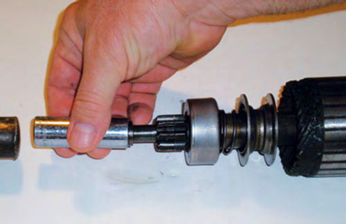
Replacing the Starter Drive
The thrust collar is usually loose and will slide off when the armature is removed. But sometimes it may remain locked to the retaining collar. If that’s the case, use a small screwdriver or pick tool to pop it free.
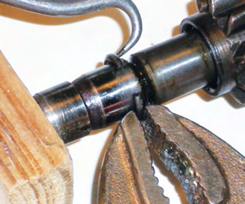
Next, the retaining collar must be pushed back to expose the snap ring. This collar secures the snap ring in its seat. In Photo 22, I am using a 5/8-inch deep socket, and a tap from a hammer to remove it. If you don’t have this socket, find a piece of scrap pipe with the appropriate inside diameter to just catch the outer edge of the collar. Photo 23 shows a close-up view of removing the snap ring. There are a number of ways to accomplish this. I simply push the ring to one side and grab it with a pair of Vise-Grips, then use a pick tool to spread the ring open, and slide it forward. Note that I have the end of the armature pushing against a block of wood. In the event I slip, this prevents the pick tool from ending up in my thumb. Once the ring has successfully been removed, slide off the retaining collar, and then the drive itself. The end result should resemble Photo 24.

Now wipe off and inspect the armature shaft for any wear or damage that might affect the proper operation of the starter drive. If all looks good, it’s time to replace the drive. Apply some silicone or graphite lubricant to the armature shaft where the drive rides back and forth. Avoid using grease, asit can attract dirt, and can also cause the drive to become sticky in cold weather.
Take the new drive and slide it on. Follow it with the retaining collar, making sure the recess in the collar is facing away from the drive so that it can be slid over the snap ring.
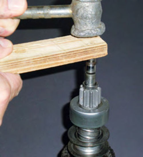
To install the snap ring, center it up on the end of the armature’s shaft; place a piece of soft wood over it and then tap it with a hammer as we have inPhoto 25. This is the easiest way to start the snap ring. It can now be pushed on the rest of the way with a 1/2-inch deep socket or small piece of pipe until it snaps into the groove.
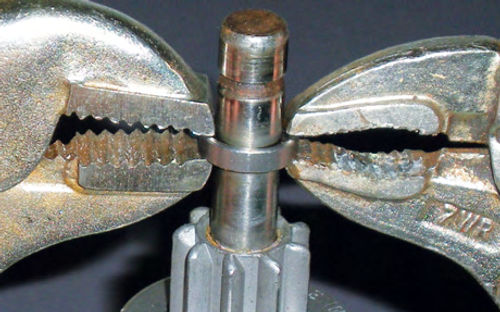
Now slide the retaining collar up until it makes contact with the retaining ring. Using pliers or Vise-Grips, as seen in Photo 26, snap the collar over the ring. The thrust collar is the last thing to go on. Note that one side is flat, while the other has a raised edge. Slide the collar on with the raised edge in toward the starter drive. The smooth edge will ultimately end up against the front bushing in the pinion housing once the armature has been installed.
In the final installment in this series, we’ll replace the bushings and then reassemble and bench test the starter.


