Restoring a small suv PT.4
Surprises Were In Store When It Came Time to Tear Down Portions of the Damaged Drivetrain.
Last month on the ’91 Geo Tracker I resolved a very difficult electrical issue, which let me get the engine running. I also fixed the gas gauge, which had been stuck on empty for a few years. Follow along this month while I go after the driveline issue that sidelined the Tracker in the first place. We have used 40 photos so far, so this month will start with photo 41.
Diagnosing the Drivetrain Issue
Now that the engine is running, it was finally time to figure out what was broken in the drivetrain. The Tracker had been in daily use, and when the clutch started slipping the owner hired someone to replace it. A short time later, the Tracker suffered a catastrophic breakdown. While pulling away from a stop sign there was a loud bang, and the engine revved to redline. The Tracker slowly coasted to a stop, dead on the road. Something had completely let go between the engine and the drive wheels.
There was no engagement at all between the engine and the drive wheels in any gear, either in 2-wheel drive or 4-wheel drive. I started my diagnosis by running the engine and testing the clutch. The clutch pedal had an odd feel to it, with the first half of the travel having almost no resistance and the second half of the travel feeling unusually stiff. The clutch pedal seemed to have no effect at all. It was almost certain that the clutch was a part of the problem. I have replaced quite a few clutches over the years, but these symptoms were a bit different than anything I had seen before.
Time for a Visual Inspection
I jacked the Tracker up and put it on stands to allow working safely underneath. I started with a good visual inspection of the transmission, the clutch linkage, the clutch cable and the pedal assembly. The clutch arm at the transmission moved properly as the clutch pedal was pressed in, and there was no evidence of the arm slipping or bending. I turned the front and rear driveshafts by hand and they turned as expected.
But everything under the Tracker had a coating of oil, so there were obvious leaks that would need to be fixed while everything was apart.
Tear Down
It would be necessary to remove the transmission and transfer case to expose the clutch assembly, then inspect the clutch, transmission and transfer case.
The first thing was to drain the oil from the transfer case. The drain plug was removed and fluid drained into a pan. The transfer case oil looked very clean, and there were minimal metal shavings on the drain plug magnet. The transmission oil was drained next. I noticed a lot of metal on the drain plug magnet, and the oil in the pan had a metallic “sheen” to it. When I poured the oil into the recycle container, I noticed a lot of fine brass particles in the bottom of the pan.
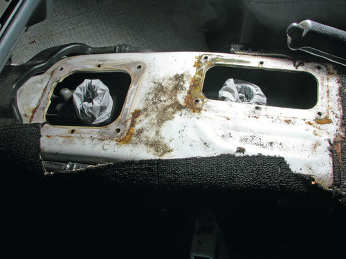
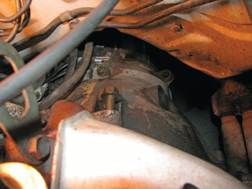
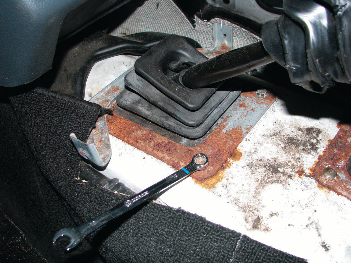
Working from inside, I removed the console assembly from between the seats. On this model there are actually 3 shift boots for the transmission and two boots for the transfer case. The upper boots keep noise, road dust and fumes out of the cab, and the lower boots seal the shifter sticks to the transmission and transfer case. I removed the upper shift boot from the transmission, then removed the lower boot and the transmission shift lever. I covered the transmission shifter assembly to keep dirt and debris out and found that my nitrile shop gloves were a perfect size to slide over the shifter assembly and seal the opening. I repeated the same steps for the 4-wheel drive transfer case shift lever and boots (Photos 41 and 42). Working from under the hood, I disconnected the battery, then removed the top two bolts from the bell housing (Photo 43). Moving under the truck, the driveshafts were then removed and set aside. The speedometer cable was disconnected, along with the electrical connections. The starter was next to come out, and was set aside.
At that point the transmission was ready to come out. I used my floor jack, along with some wooden blocks to lift and support the transmission. For safety, I also added a strap from the top of the transmission up through the shifter hole and connected it to the seat rails to prevent the transmission from dropping before I was ready for it to come down. I removed the transfer case crossmember, then removed the remaining bell housing bolts. Working carefully, I separated the transmission away from the engine, and slid it backward about 2 inches to fully disengage the input shaft from the clutch disk and for the bell housing to clear the clutch assembly. I lowered the floor jack until the transmission was as low as it would go while still on the jack. I then rolled the entire assembly out from under the Tracker and took it outside for a thorough cleaning and inspection.
What Happened To That Clutch?!


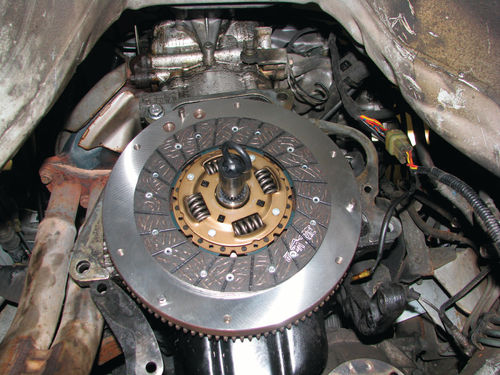
With the transmission out, it was immediately obvious that the clutch disk had come apart. A piece of the friction material was sticking out past the side of the pressure plate. The center hub of the clutch disk had completely broken loose from the friction material and was spinning free (Photos 44 and 45).
These trucks use a roller bearing for the pilot shaft, rather than a bronze bushing like some vehicles. The roller bearing had not been replaced with the clutch. The cavity behind the bearing was full of metal shavings, and the bearing felt very gritty when rotated by hand. The pilot bearing should always be changed with a clutch, and this one was definitely shot.
I cleaned up the flywheel in place using brake clean and paper towels first. Then I used a pneumatic die grinder with a roll-lock “clean up disk,” which is essentially a rotating Scotch Brite pad. The flywheel surface could be re-used in a pinch, but it had a lot of heat discoloration and glazing. To do a proper job I would need to resurface the flywheel so that the disk has a proper surface to mate with. I removed the flywheel and pilot bearing as a unit, then tapped out the old bearing. The flywheel was taken to a local machine shop where it was ground and refinished to a like-new condition.
And the Transmission Too?
Next, I turned my attention to the transmission. The exterior was very greasy, and the inside of the bell housing was covered by a thick mixture of oil, clutch friction material, and metal shavings. I sealed up the driveline and shifter openings to ensure they were watertight. Next, the transmission and transfer case were liberally sprayed with engine degreaser, then washed off with a pressure washer. It took a few passes on the stubborn areas, but the parts cleaned up nicely. The crossmember was cleaned of grease and oil the same way.
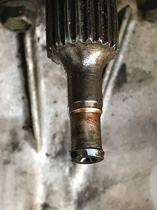
I inspected the transmission and made a very unpleasant discovery. The failed pilot bearing had been spinning on the input shaft, and had ground down a very deep gouge into the pilot area of the shaft. More than 65 thousandths of an inch of metal had been worn away! Additionally, moving the input shaft side to side showed significant lateral movement, indicating the transmission main shaft bearings had also failed (Photo 46).
That much side play would allow the clutch disk to wobble severely any time the clutch was disengaged, and certainly that is what caused the clutch disk to come apart the way it had. The transmission would require a new input shaft and complete rebuild before being used again, assuming it could be saved.
At this point, a transmission rebuild would have taken time and attention away from other aspects of the project. I was very fortunate to source a good used transmission and transfer case locally for a fair price. This let me get the project back on track.
Working With the Replacement Clutch

The resurfaced flywheel was installed onto the engine, using medium-strength (blue) thread locking compound on the bolts and torqueing to factory specs. One question that comes up occasionally is how to hold the flywheel from turning while you tighten the bolts. There is more than one way to do it. In this case, the easiest thing was to thread a spare bolt into the outer edge of the flywheel where the pressure plate mounts. I put a breaker bar between the bolt and a dowel pin and held the breaker bar while I torqued the flywheel bolts. Photo 47 shows how the breaker bar held the flywheel, which worked like a charm.
The flywheel surface was given one final cleaning using brake cleaner and a paper towel to get off any grease or contaminants. The new pilot bearing was installed in the flywheel and gently tapped into place until it was seated. Note that I used a large socket that only pressed against the outer bearing race, rather than hammering directly on the bearing surface.
The clutch kit came with an alignment tool, which is nice because it ensures the installer has the proper size. The new clutch disk was slid onto the alignment tool, then the tool was inserted into the pilot bearing. This holds everything in proper alignment when the pressure plate is installed over the clutch disk (Photo 48). The pressure plate bolts were started in the holes.
It is important to tighten the bolts evenly when installing the pressure plate. I like to tighten the bolts in ½-turn increments in a star pattern so every bolt gets tightened a little bit at a time. When all bolts had completely pulled in tight, they were torqued to factory specifications.
Transmission Installation
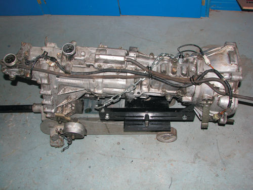
I cleaned the replacement transmission and transfer case, then transferred several bolts and brackets from the old to the new. I also replaced the driveshaft output seals to prevent any leaks. I equipped my floor jack with a transmission jack adaptor and prepared the transmission for installation (Photo 49).
I rolled the transmission and transfer case under the Tracker and then jacked them up. But at this point I ran into an unexpected problem. The width of the transmission jack adaptor caused it to hang up on the bottom of the Tracker, and I could not raise the transmission high enough to install it. I have used that transmission adaptor successfully on my ’55 Bel Air and a few other projects, but the transmission tunnel is narrow on the Tracker and the transmission is very high in the chassis so it requires a different tool.
Building a Jack Adaptor
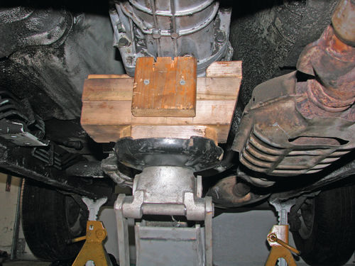
The expression “Adapt and Overcome” became the motto for the solution to this problem. Using 2x6 lumber I cut and notched several boards to create a wooden cradle that fit the bottom of the transmission and transfer case, but did not stick out any wider than the widest part of those components. I made notches and reliefs where needed until it fit the transmission, then screwed all the wooden pieces together to make a solid adaptor (Photo 50).
I lifted the transmission, this time using the new adaptor, and was able to take it all the way up the full height and aligned the transmission input shaft to the clutch disk. Once again, I installed safety straps from the transmission up through the shifter holes to the interior to make sure the transmission would not fall when I was working underneath. Better safe than sorry.
It is very important to keep the transmission in proper alignment with the engine while it is slid forward into place. To help with alignment I temporarily installed an 8” long bolt on each side of the transmission bell housing through the corresponding engine bracket holes. When everything was lined up well, I pushed the transmission forward until it mated up tightly to the engine. It slipped right in very smoothly, which was very satisfying.
From there installation was the opposite of the tear down. The bell housing bolts were reinstalled and tightened, then the transfer case crossmember was installed. The starter was installed and the electrical connections were reattached. The shift levers were cleaned. A light coating of grease was put on the pivot balls, and they were reinstalled. The upper and lower shift boots were reinstalled. I also took the time to clean up and paint the shift boot retainers so everything is rustfree and looking good.
The last thing was to adjust the clutch cable to take out the cable slack, leaving just enough free play to let the clutch fully disengage and not have any cable preload.
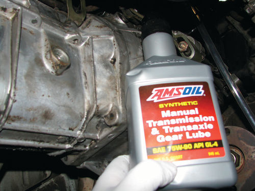
At this point, everything was installed except the drive shafts. The front drive shaft runs past the side of the transmission so it was easier to fill the transmission with oil before installing the drive shaft. The drain plug was sealed with RTV silicone, per the factory service manual recommendation. The transmission was filled full with fresh GL-4 transmission fluid, using a hand pump screwed into the gear lube bottle (Photo 51).
A Note About Gear Lube
It is getting harder to find GL-4 transmission fluid that is intended for manual transmissions with “yellow metal” components, which is what Suzuki recommends. One local parts store stocks GL-4 that is labeled as compatible with brass components, so that is what I used. There is a lot of debate whether it is safe or not to use GL-5 gear lube in a manual transmission, and some people use it without problems. Fortunately, I was able find the recommended oil which is the best way to go.
With the transmission serviced, I installed the front drive shaft but waited on installing the rear shaft so it was easier to access the transfer case fill plug. I filled the transfer case with gear oil, again using a hand pump and hose. After the transfer case was topped off and the drain plugs installed, I installed the rear drive shaft.
Preparing a New Fuel Injection Wiring Harness
When I had the transmission removed I discovered that opened up access to the bottom side of the engine, making it much easier to get to the damaged wiring we discussed in the July issue. I took advantage of that opportunity to pull out the old wiring harness and repair the damage. The stock wiring harness routing is along the engine block at the bottom side of the intake manifold. This is not a safe location for the wires to run as it allows the harness to chafe and short out.
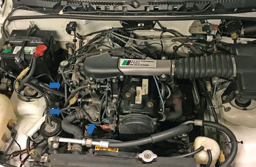
The damaged harness has wires for the computer to open and close the vacuum control valves, which were the wires that shorted out. In addition, that harness has wires for the alternator, the temperature gauge, the oil pressure indicator lamp, and a signal ground wire. I routed the wires over to the right-hand inner fender well, which is a much safer location. This should prevent any future issues (Photo 52).
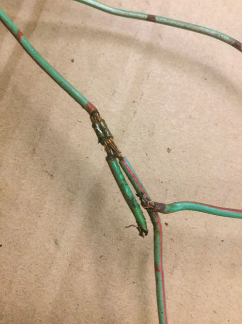
I disconnected all of the connectors and clamps, then carefully pulled the wire harness all the way back to the firewall. I removed the electrical tape wrap to expose the individual wires, then inspected each wire for chafing or heat damage. Three wires were damaged, so they were replaced (Photo 53).
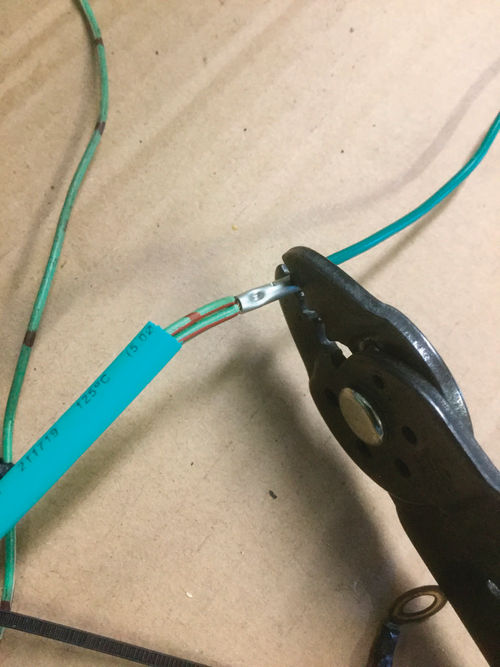
One at a time, each wire was routed to the new wiring harness location and measured to determine if it needed to be lengthened or shortened. Any wire splices were made using crimped and soldered connections, then covered with heat shrink tubing (Photo 54).
After the wires had been adjusted for length, they were routed along the new wire harness location. When all wires were in place, I installed temporary zip ties about every 6 inches to hold the bundle together. I then wrapped the new wiring harness with silicone tape from the firewall all the way to the end of each wire run, removing the temporary zip ties as I went. The wire harness was permanently installed and all wires connected. Everything works properly, and I am confident this is a lifetime fix for this Tracker.
Now It Runs and Drives Very Well
It was finally time to get the Tracker back on the road. I reinstalled the wheels and tires, lowered it to the ground, and rolled it outside. After firing up the engine, I checked the operation of the clutch, transmission, and transfer case and all worked well. I took a short test drive, and was very pleased with how the little truck drives. There is certainly a lot of work remaining on this project, but it was a great day when I was able to drive it out of the shop under its own power. Follow along next time while I inspect and tune the engine and tackle a number of smaller projects.


