Restoring a Small suv PT. 3
This Time We’ll Be Patiently Pursuing Two Wiring Problems. One Controls the Fuel Gauge… and the Other Keeps the Engine From Running.
Editor’s note: For a look at a reader who’s been driving her Geo Tracker for the past 24 years, see page. 9.
Our current project vehicle is a low-mileage 1991 Geo Tracker 4-wheel drive mini-Sport Utility Vehicle that was once well cared for, but had fallen on hard times. Last month I cleaned up the moldy interior and fixed the dragging brake. Follow along this month while I resolve an electrical issue, get the engine running and fix the gas gauge. We have used 29 photos so far, so this month will start with photo 30.
Diagnosing the Lack Of Spark
It was time to determine why the Tracker will not run. At the beginning of this project, I did some basic troubleshooting and determined that there was no spark. With the truck back at my shop, I started troubleshooting where I left off by testing the spark. I unplugged the coil wire from the distributor cap and plugged a spare spark plug onto the end, then grounded the plug against the engine. When I cranked the engine over there was no spark at all. I started with the coil wire rather than a plug wire because this let me rule out a broken rotor or distributor cap. I also measured the resistance of the coil and it was within specifications. This indicated the lack of spark was something upstream of the coil.
Check Engine Light—The Canary in the Coal Mine
One of the first things I noticed was that the Check Engine Light (CEL) never came on when the key was turned on. That is an important clue, because the CEL should always come on when they key is turned on and the engine is not running. This indicated that either the computer was not powering on or the light itself did not work. Without a working CEL, it would be impossible to read any error codes that the computer stored. I also noticed tape glue residue on the instrument cluster where gaffers tape had been used to cover up the CEL. Taping over a warning light is never a good idea!
Blown Fuses
Starting with the obvious, I checked the fuses in the fuse panel, which is located under the dash, right above the driver’s left knee. Most of the fuses were OK, but I found the Fuel Injection (FI) fuse was blown. I had a spare fuse on hand, which I installed. The replacement fuse blew as soon as I turned on the key and the main relay tried to pull in. Uh oh—that isn’t a good thing. That blown fuse started a long odyssey of troubleshooting wiring until I eventually found the short circuit.
Wiring Troubleshooting— One Step At a Time
If there is any advice I would give someone who is troubleshooting wiring it is to have good wiring diagrams, and go slowly and methodically while you work your way through the system.
The problem with short circuits is that they can occur anyplace in that wire run, so finding them can be quite a challenge. It took me several days to chase down this short, and there were times when I started to doubt my ability to find it. But in the end, I kept working until I figured out where the wire was shorted. Once found, fixing the short was pretty simple.
The key is to figure out how to isolate the system into logical chunks, and test them one at a time until the problem is found. This can be a slow and tedious process, which can require a lot of time and patience.
Time To Ask For Some Advice
Working on wiring and electrical systems can be much more difficult when working on a vehicle from the ’90s than say a vehicle from the ’40s or ’50s. There are a lot more systems involved and significantly more wires, so it is very important to have a good set of wiring diagrams and manuals to use for troubleshooting. I did not have any factory service manuals for the Tracker so I ordered a complete set from a used book store, which was an excellent investment. In the meanwhile, I was able to find some wiring diagrams on the Internet for a similar Tracker, which were pretty handy for starting my troubleshooting. Armed with wiring diagrams and some good ideas, I was able to get to work (Photo 30).
I was also able to find a number of excellent resources and Suzuki owners’ groups on the Internet, which was incredibly helpful. I found some articles on a website called Fix-kick. com that gave me some excellent ideas of things to check out. Additionally, I joined an owners’ group web site called Suzuki Forums (www.suzukiforums.com). I was able to ask some questions and correspond with several people with great ideas of where to check. In the end, the problem I had was identical to an issue another owner had encountered on his Suzuki. This is one of the advantages of working on a vehicle that has a passionate and helpful group of people who follow them. I can’t say enough good things about the Suzuki moderators and owners who offered information, hints and advice.
The Master Relay and Computer
As they say, the best place to start is at the beginning. In this case, that is the master relay and Engine Control Module (ECM), which many people casually refer to as the computer. When the ignition key is turned on it activates a main relay, which in turn powers on the ECM, the ignition system, and a number of fuel-injection components. The ECM in turn activates the fuel pump relay, pressurizing the fuel system.
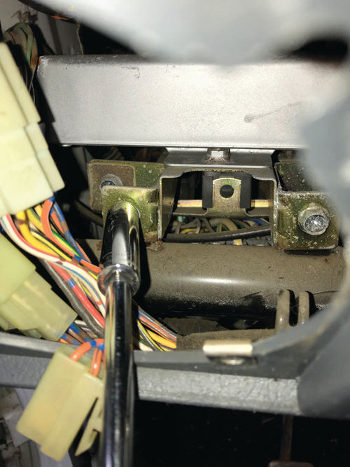
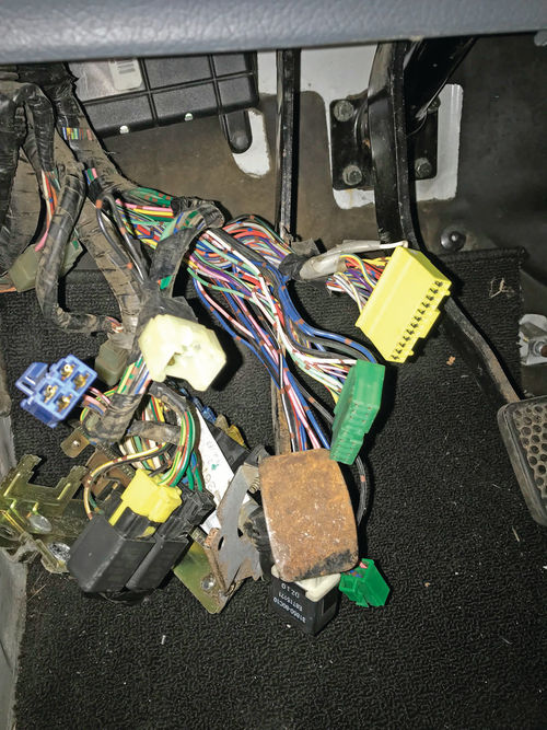
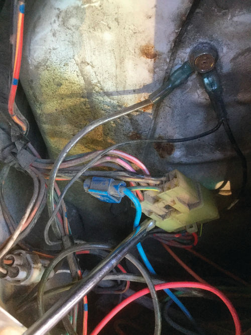
On this model, the ECM, relays, and fuse box are all mounted to a bracket behind the dash, above the driver’s legs. I am a fairly big guy, and working in this small space would be a challenge, so I started by removing the driver’s seat to make more room to work. I removed the left side speaker assembly, then working through the hole I was able to unbolt the bracket from the dashboard structure (Photos 31 a&b). This allowed the entire wiring assembly to be lowered where it could be worked on. It looked very intimidating, but by going methodically and paying careful attention to the connector and wire colors you can make sense of it (Photo 32).

I removed the master relay and unbolted and removed the computer. I inserted a new fuse, then turned on the key. The fuse held, so I knew the basic wiring harness to the relay and ECM was good. This particular series of vehicles up through 1996 has a notorious issue with defective capacitors in the ECM, which can cause a number of problems. The fix to the computer only has to be done once for the life of the vehicle, so once it has been repaired it should be good forever. Our project Tracker already had a rebuilt ECM installed with the lifetime fix incorporated. At this point I knew a few important things, namely that the computer was healthy and that the master relay was switching in the short. Time to go back to the wire diagrams.
Chasing That Blue and Black Wire
The wiring diagram showed that the wire I was concerned about was a blue wire with a black stripe that provides power to pretty much all of the fuel injection components all over the engine and under the dash, as well as to the ignition system. I disconnected the connector from every component under the hood that the blue/black wire is connected to. I disconnected connectors at the distributor, the idle control valve, and three vacuum control valves. I also left the ECM and the fuel pump relay uninstalled. I tested the output wire from the main relay with my voltmeter (set to ohms) and verified that the short circuit was present. The short circuit persisted so the hunt was still on.
Some Handy Tools
There are a few tools that would have made it easier to find the short. Unfortunately, I did not have these tools in my toolbox. At the top of the list would be a clamp-on ammeter, which could be used to determine which wire or wire bundle was drawing power. This method requires a way of keeping power on the shorted circuit using a current limiting power supply or putting a load across the fuse (such as a light bulb). One tool that I did try out was soldering a small side marker lamp across the back side of a blown fuse to serve as an indicator of the short. This method worked well, but I had trouble with the soldered wires breaking off the back of the fuse. If I had to do this all over again I would buy a fuse extender and solder the wires to that. In my case, I kept going with my basic troubleshooting. It took a while, but eventually I figured it out.
Performing Automotive Exploratory Surgery
At this point, I was convinced the issue was a short in the wire bundle. I started under the hood, and inspected the wire harness coming from the right side of the firewall, but did not find any faults.
Using an X-Acto knife I carefully removed the electrical tape that wrapped the outside of the wiring harness just forward of where it exited the right side of the firewall. I found the factory splice where the main wire split off to run to the distributor, the idle air control valve, and the vacuum valve for the charcoal canister. I carefully cut the factory splice, isolating the engine wiring from the wiring under the dash. The short persisted, so I knew that the wiring harness under the hood on the right side was good. I carefully labeled and temporarily taped up the wires, but I did not put the splice back in at that point. I waited until the end of the wiring project to restore all splices.
More Exploring
I carefully inspected the wiring inch by inch under the dash from the right side to the left. The wiring all appeared to be in good shape and I could not find any issues. While I was under there I did find evidence that someone had been working on the wiring previously. I found a number of cut wire ties and unplugged connectors for accessory systems, which I was able to quickly troubleshoot and correct. It would seem that I am not the first person to chase after this wiring gremlin.
On the Right Track
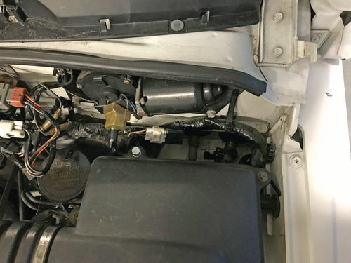
By this point, I had worked my way back to the computer and main relay. More studying of the wiring diagram and more testing showed that the problem was not the warning buzzer or the fuel pump relay. I traced another branch of the blue/black wire out of the main relay to the ECM, then on to the left side of the firewall. Again, I carefully cut out a factory splice where four wires come together. This time I was fortunate. By removing the splice, I had isolated the short circuit. Using my digital volt meter, I was able to identify which of the four wires had the short. I tracked the shorted wire out to a connector near the firewall, where it continued through the firewall and back under hood on the left (driver’s) side. When I unplugged that connector, the FI fuse held with everything else hooked up (Photo 33).
Finding the Short
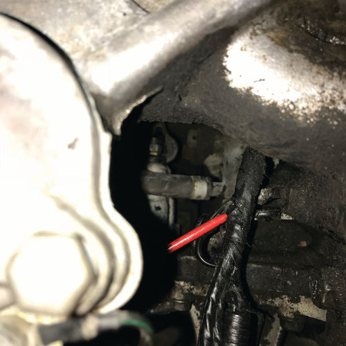
From that point, the troubleshooting went very quickly. I was able to trace the shorted wire (which changed colors at the connector to green with a red stripe) as it ran across the firewall, then turned and ran forward under the intake manifold. It was very difficult to see the wiring harness because it was buried very deep under the intake. But looking carefully, I finally found the culprit. The wire harness had chafed against a metal bracket under the intake manifold near the thermostat housing. Over time the wiring insulation wore through and the wire shorted out (Photo 34).
Just like that, the problem was finally revealed. All of the wires in that bundle were damaged, and were almost certainly the cause of the previous engine drivability issues. During the time the vehicle sat, the damaged wire insulation must have finally broken down the point where the wires made a dead short to the engine.
Restoring the Factory Splices…
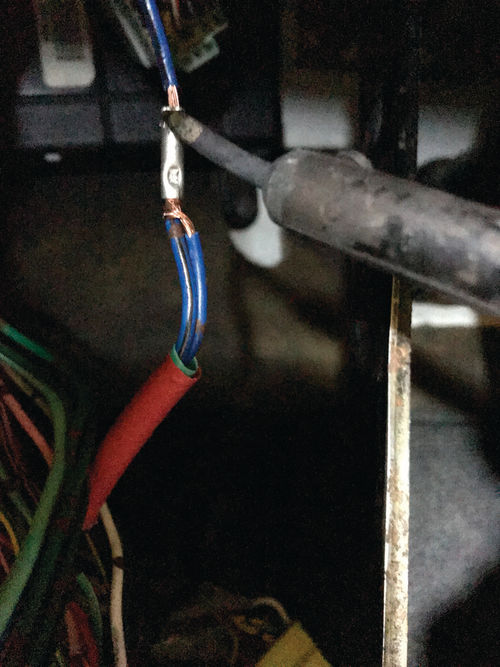
I restored the factory wiring harness splices I had cut out using soldered connections for longevity. I crimped a bare coupler over the wires and then soldered the coupler. Next, I covered the coupler with heat shrink tubing to insulate the crimps. To finish the job, I used silicone tape to wrap up the wiring harnesses, as I feel it provides better protection for the wires than the factory-style electrical tape. I reinstalled the bracket that holds the computer and fuse panel, and tidied up the wire bundles with zip ties (Photo 35).
…And Now It Runs
I made a temporary repair to the shorted wiring harness with electrical tape to allow the engine to run. When I turned on the key, the Check Engine Light came on as expected, and the F1 fuse held. I have since built a new wire harness and routed it in a safer location, which I will discuss in a future article.
At that point I rolled the Tracker outside, added some fresh gas to the tank, and cranked up the engine. It started right up, and the Check Engine Light went out, which made me very happy. For the first time in a very long time our project truck has a running engine!
Fixing the Fuel Gauge
With the engine running, I was able to turn my attention to other things. For example, the fuel gauge was not working. The needle was stuck below empty and did not move when the key was turned on, even after I added a few gallons of gas. Fuel gauge issues can be caused by a bad ground, a bad connection, a bad sending unit, or an issue with the gauge itself. In my experience it is always best to start troubleshooting back near the gas tank, since that is where most problems originate.
On this model, the wiring connections to the rear body are accessed through the left taillight housing, which makes things very convenient. I removed the left tail light, and inspected the wiring. I checked the grounds to make sure they were clean and had good electrical contact with the body. Next, I unplugged the connector where the fuel gauge wire passes from the rear body up to the gauge. I ran a quick test by connecting a light bulb from the fuel gauge wire to ground, then turned on the key. The fuel needle started slowly rising, indicating that the gauge was working and the wiring was good from that point forward. Note that in early versions of the factory service manual it says that it is OK to ground this wire for up to a minute, but later versions of the manual recommend hooking up a small light bulb to run the test, since the extra resistance of the light bulb will prevent the fuel gauge from overheating (Photo 36).
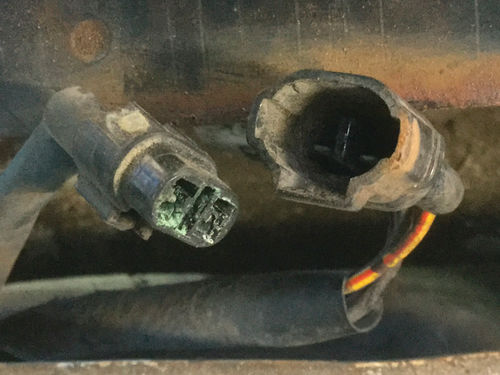
This indicated that the gauge and wiring are good from the taillight forward. The next thing to check is the connector between the wiring harness and the sending unit. The connector sits at the back of the gas tank, and is exposed to the elements so it is not unusual to have corrosion in that area. Accessing the connector requires taking off the rear bumper cover, which exposed the wires for the fuel sending unit and the fuel pump. Opening the sending unit connector revealed the problem—there was significant corrosion in the connector (Photo 37).

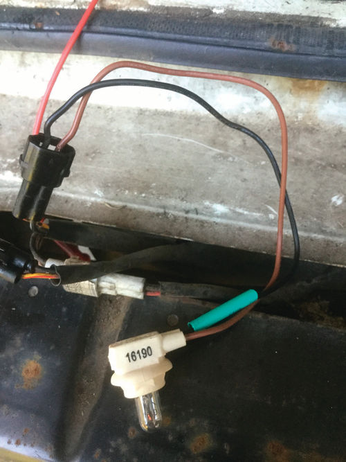
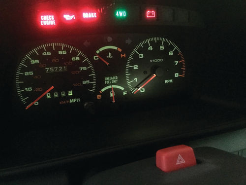
I set about to clean the connector, using WD-40 and a cotton swab to reach down inside (Photo 38). After the connector was clean, I tested the gauge by connecting the small light bulb directly between the signal and ground wires. The fuel gauge responded as it should, and the light bulb glowed dimly, which proves all of the wiring end to end (Photo 39). I plugged the connector together, then wrapped the connector with silicone tape to reduce the chance of future corrosion. The fuel gauge is now working properly (Photo 40).
Follow along next month when we finally go after that catastrophic driveline failure.


