
Restoring a small suv PART 5
Several Tests and Adjustments Were Made On the Engine and a “Self-Taught Trick” Located an Exhaust Leak. It’s Also Time to Work On the Instrument Panel.
So far, things are progressing nicely on the 1991 Geo Tracker project. I found and fixed the clutch and transmission problems, as well as finding and fixing a shorted fuel injection wiring harness that prevented the engine from starting. I also cleaned out and de-toxed a major mold infestation from the interior caused by improper storage.
Now that our little SUV is running and driving, this opens the way for a number of other jobs. We have shown 54 pictures so far, so this month we will start numbering at 55.
Inspecting the Engine
The previous owner told me the Tracker had a history of setting the Check Engine Light intermittently. It had had been worked on numerous times by a few different mechanics, but the problem always came back. I am confident that these issues were caused by the shorted fuel injection wiring harness we resolved in Part 3. I scanned the computer which showed no fault codes and the Check Engine Light is off, and I don’t expect these problems to return.
I test drove the Tracker for several miles to check out the overall condition of the vehicle. There is a definite engine oil leak coming from the valve cover gasket, but the other notorious leak places like the distributor were clean and dry. Fixing the oil leak was very high on my list, before the mess came back. Also, I could hear and smell a big exhaust leak from somewhere in area of the exhaust manifold, hidden underneath a metal heat shield.
Removing the valve cover would be a good opportunity to perform a valve adjustment and inspect the top end of the engine while I repaired the oil leaks. The valves on this model are manually adjusted, which is an important service item that needs to be performed every 50,000 miles. I also suspected that there may be low compression in one cylinder, based on the way the engine sounds when it is being cranked over by the starter.
The cranking speed surged every other revolution, which is a concerning symptom. A compression test could be run any time, but valve adjustments affect compression so it makes the most sense to check the valve lash first; then run a compression test afterward.
Valve Adjustment
I removed the air cleaner assembly; then removed the upper air intake manifold, since it sits across the top of the engine and bolts to the throttle body assembly.
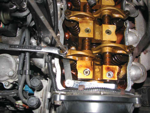
Each spark plug wire was labeled, and then unplugged and moved out of the way. The 4 valve cover bolts were removed, and then the cover was carefully pried up and off the engine. Overall the interior of the engine was clean, with no visible sludge deposits. The valve cover gasket was very hard and brittle, and had been patched together with blobs of RTV silicone. This tells me that at some point the valve cover has been removed and improperly put back with an old gasket (Photo 55).
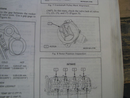
The valve adjusting procedure for the Tracker is very similar to many other overhead valve engines I have worked on over the years. I found the detailed procedure listed in the factory service manual to be excellent and it made the valve adjustment easy. First the crankshaft is rotated until the rotor is pointing at the #1 spark plug terminal, putting the piston at top dead center on the compression stroke. At that point, the manual shows which valves can be checked. I measured the valve lash for each valve, using a feeler gauge between the valve stem and the rocker arm to measure how much clearance there is between each valve stem and rocker arm. I wrote down each valve measurement (Photo 56).
Once I had measured the valves, I adjusted the ones that were outside of the cold valve lash specification. The valve adjustment is made by loosening the lock nut with a wrench, then turning the adjustment screw in or out until the feeler gauge can slide with light resistance. Then the lock nut is retightened. Sometimes tightening the locknut can affect the measurement so take your time until they are all properly adjusted (Photo 57).
After the first half of the valves were adjusted, I rotated the engine until the distributor rotor was pointing at the #4 terminal, indicating the #4 cylinder was at top dead center on the compression stroke. I checked the remaining valves, writing down the clearances and adjusting the lash to specifications.
I found that two of the valves were very loose, which I quickly corrected with the adjusting screw. Unfortunately, I also found two valves were significantly over-tightened. The biggest worry was the #1 exhaust valve, which had no lash whatsoever. That is very bad because it means the exhaust valve was never able to fully close. This results in compression loss, and if driven this way for long will result in a burned valve.
There was no way to know how long the engine had been run in this condition but it was cause for concern.
Compression Test
After adjusting the valves, I ran a compression test to measure the health of the engine. All sparkplugs were removed, noting the condition of each plug as it was removed. There was no evidence of oil fouling and the plugs looked fairly good overall.
A compression gauge was screwed into the spark plug hole of each cylinder in turn, and the engine was cranked over through 4 compression strokes. The compression on cylinder #1 was very low, measuring only 65 PSI while the other cylinders measured around 170 PSI (Photo 58).

Next, I conducted a “wet” compression test on the #1 cylinder to determine the cause of the low compression. I started by squirting a few tablespoons of oil into the sparkplug hole with an oil gun, then repeated the compression test.
The purpose of the oil is to help temporarily seal the piston rings. If the low compression is due to a ring problem the compression should rise quite a bit, but if not, that indicates a problem with the cylinder head. In my case, the compression numbers were unchanged which indicates a valve problem (Photo 59).
Finally, I turned the engine over again until the #1 piston was at top dead center on the compression stroke so both valves would be closed. I threaded an air fitting in the spark plug hole and put compressed air into the cylinder. Listening carefully, I could hear air leaking in the exhaust manifold and out the tailpipe. This is very disappointing news. For now, I replaced the valve cover gasket and buttoned up the engine.
This problem is likely to only get worse over time, so before this project is complete the cylinder head will have to come off to get a valve grind.
Finding the Exhaust Leak
I also needed to isolate the source of the exhaust leak so I could get the necessary parts and seal it up at the same time I made the other engine repairs. I could tell the leak was coming from the area of the exhaust manifold, but I couldn’t tell if it was coming from the top where it bolts to the head, at the bottom where the downpipes bolt on, or if the manifold itself was cracked. Knowing the source of the leak would ensure I had the proper parts on hand to fix it properly.
First, I removed the tin heat shield from the top of the exhaust manifold so I could see well, then gave everything a good visual inspection. I noticed a number of missing manifoldto-cylinder head bolts—about half of the bolts were gone! I am sure there must be a story behind that, but I can only speculate. With that many bolts missing, there would not be adequate clamping force to keep a good exhaust-tight seal between the head and the manifold.
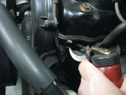
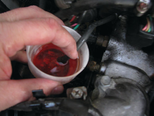
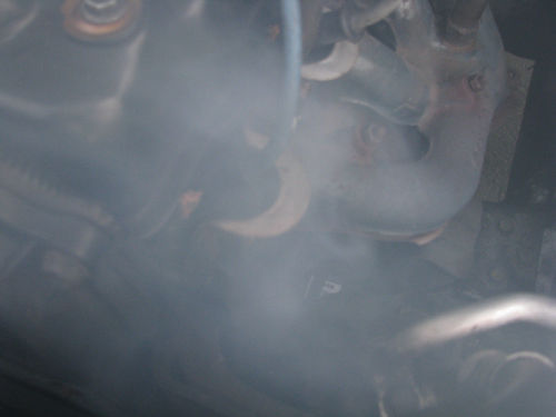
I will share a little self-taught trick that makes finding exhaust leaks very easy. I poured a small amount of Marvel Mystery Oil into a small container, then removed a vacuum hose that is connected to the intake manifold. With the engine at idle, I placed the end of the vacuum hose in the oil, and let the engine slowly suck it up into the combustion chambers. As soon as the throttle is blipped the exhaust will start smoking a heavy whitish gray smoke that will instantly reveal all exhaust leaks. You can also use top cylinder lubricant or automatic transmission fluid as an alternative to Marvel Mystery Oil.
The smoke test confirmed a large exhaust leak coming from where the head and manifold meet. The bolts and gasket will both need to be replaced when the cylinder head is removed for the valve grind. The manifold and downpipe appeared to be well-sealed (Photos 60 and 61).
Battery Box Repairs
The best feature of our Tracker is that it is nearly 100% rust free, which is fairly rare for these little trucks. The only rust anywhere on our SUV was in the battery tray. Overall the battery tray is in excellent condition, with the exception of the front lip which had rusted away to just a few scraps. Battery acid must have leaked down at some point and caused the metal to rust. This is a required repair, because without it there is nowhere for the forward battery hold-down bolt to attach to the chassis. Having the battery properly bolted down is very important on any car, and is critical on an SUV or any off-road vehicle.
The battery tray is welded to the inner fender well, so a full replacement would be a big job. The good news is that the damage was very minor and easily fixed using a piece of angle aluminum, rivets, and POR-15 paint (Photo 62).

I started by trimming away the last of the damaged metal, then removing the surface rust. I measured and cut a piece of angle aluminum to the length of the battery box, then rounded all of the corners and edges. I drilled a hole for the battery hold-down bolt, and test fit the part. When I was satisfied with the fit, I drilled holes in the angle bracket and mounting holes in the battery tray for rivets, but did not attach it in place yet.
Next, I applied a coat of POR-15 (paint over rust) paint on the entire battery tray using a disposable foam brush. Note that I applied paint after drilling for rivets so that the rivet holes would be sealed with the POR-15. It’s important to prevent rust from finding even the smallest place where it can get started. The paint was allowed to cure overnight, creating a very hard barrier coating to seal the metal including the new rivet holes (Photo 63).

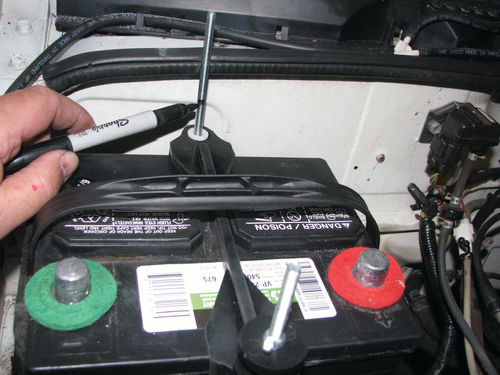
Once the paint was dried, I riveted the new angle bracket in place, then reinstalled the battery. New battery hold-down bolts were installed and marked for the proper length with a permanent marker. I removed the bolts and cut them on the bench with a hacksaw, then ground and chamfered the ends. I completed the installation by reinstalling the bolts, hold-down bracket, and nuts to clamp the battery down to the chassis. This is a very solid repair that should last a very long time (Photo 64).
Instrument Cluster
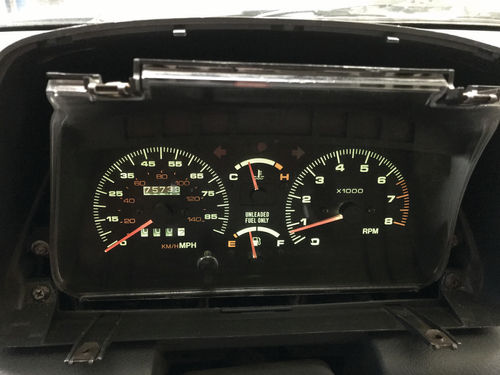
With the Tracker running and driving it was possible to test all of the dashboard instruments and lights. On the good side, all exterior lights worked properly. The speedometer and temperature gauges worked. The fuel gauge also worked properly following the repairs discussed in Part 3.
Not surprisingly, I also found a number of problems that needed to be fixed. The very first thing I noticed was that the tachometer was essentially unusable. When the engine was started, the tach immediately jumped from zero to about 2000 rpm and froze there. Revving the engine caused the needle to jump up to 3200 rpm and stay there, no matter what the engine speed was. However, when the key was turned off the needle would immediately drop back to zero.
The problem definitely was not a “sticking needle” since the reading always returned to zero as soon as the key was turned off. Basic troubleshooting indicated the problem was almost certainly the tach itself.
I also noticed that several of the indicator lights did not work, and some of the display back lights were out. Also, on the face of the gauges there was tape residue where someone had once used gaffers tape to cover up the check engine light, which is a really bad idea!
I removed and inspected the instrumentation cluster. There was evidence of exposure to high humidity and moisture. The back of the gauges showed corrosion where the printed circuit board is screwed to the gauge assemblies. I cleaned all of the electrical connections, but that only resolved a few of the issues.
I bought a used instrument cluster assembly from a Suzuki used parts dealer and had it shipped to my shop. I temporarily installed and tested the replacement cluster, which completely resolved the tach and indicator lights issues. That could have been the end of the story, but I wanted to retain the original, correct 75K-mile odometer reading. The replacement had roughly double that mileage (Photo 65).

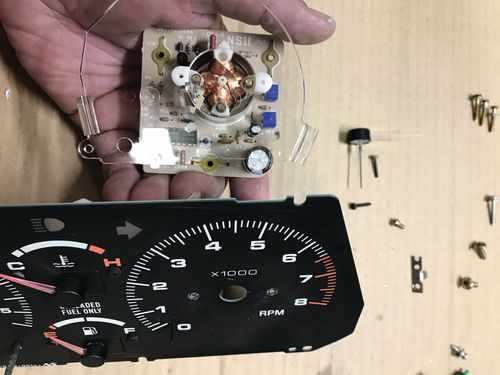
I elected to combine the parts from both instrument clusters into a single working unit. This would get everything working properly, and let me keep the correct original mileage reading. I disassembled both instrument clusters, inspecting everything as I went. I used the original speedometer, fuel and temperature instrument assemblies, combined with the replacement tachometer, printed circuit board, and housing. This sounds like a big job, but it only took about 30 minutes, including time spent cleaning and polishing the plastic lens inside and out (Photo 66).
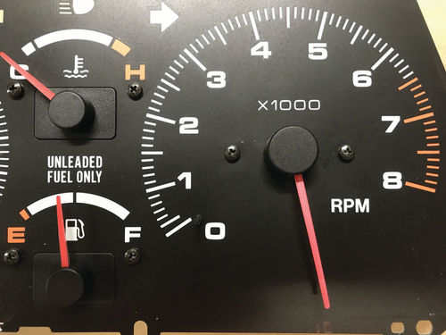
The only tricky part of the job was to ensure the tachometer needle was reinstalled in the correct position when the instrument was put into the new panel. Before removing the needle from either gauge, I turned each tach needle clockwise, well past the redline until the return spring brought it to rest at approximately the 5 o’clock position. I used a marking pen and noted the needle position at rest on both gauges, which was the same position for both. Then I carefully removed the needle and moved the working tach into the original panel. I reinstalled the needle onto the tach, ensuring it was properly lined up before pressing it onto the shaft. The instrument cluster was then reassembled and installed. The results were a fully working instrument panel with the original, documented mileage showing on the odometer. All gauges and lights now work, so the results were definitely worth the extra effort (Photos 67 and 68).
Follow along next time when we turn our attention to restoring the interior and make a number of cosmetic repairs.


