Lighting Upgrades, Pt. 3
Our Articles On Vehicle Lighting Brought Many Comments. Here Are Some Along With the Author’s Replies.
IMPROVING THE LIGHTING systems in vintage rides is an important topic for those that drive their vehicles on today’s roadways. Many of you obviously agree,based on the feedback to the Lighting Upgrades articles in the February and March issues. Here’s some of the reader responses along with commentary from Mike Harlan, author of the articles.
There were 10 photographs in the first two installments, so we’ll start here with Photo 11.
Electrical Grounds: Backbone of the Lighting System
Reader Ray Guarino writes: Mike Harlan did a fine job of introducing the reader to several affordable options available where upgraded lighting is concerned, but I feel there should have been a stronger emphasis on the backbone of the system. I’m Referring specifically to electrical grounds(existing and additional), and the addition of modern relays to power the higher-draw lighting components. Without good grounds, electrons can’t complete their circuit paths and, more commonly, voltage drops occur which reduce the power available to a device.
Mike’s response: Ray is absolutely correct on both points. I had always intended to write another wiring article and touch on these points, so let’s do that now. In order to have great lighting, you need to have full voltage to the lights. This applies to all the other electrical components as well. Sounds simple,right? It should be, but that is not always the case, especially when dealing with a decades-old vehicle. When we talk about the voltage to a light (or other electrical component), we are talking about the difference between the positive and negative wires, measured at the bulb socket, with the lights on. For lighting, the effects of low voltage have a serious effect. A 10% reduction in voltage reduces the light output by 27% for tungsten bulbs and by 30% for halogen!
Electrical Grounds: In an electrical system, any resistance between the battery and the device is robbing vital power from the light or other electrical device. The ground side of the electrical system is equally as important as the powerside, and there are many more places for connections to go bad.
So, how do you know if your grounds are good? We do that by measuring the voltage between the battery ground terminal and several other strategic locations. If the system has good grounds, the voltage measurements will be near zero.
I like to start by measuring the grounds between the negative battery terminal, the engine block, the frame (if so equipped), and to the body. This is the foundation, or backbone, of any good electrical system. I will refer to it as the ground plane. The vast majority of cars use rubber mounts between the engine/drive train and the frame/body (to reduce noise and vibration). Since the rubber mounts act as an electrical insulator, there needs to be another grounding strap or cable to complete the electrical path. Improper engine grounds can lead to poor light performance, slow cranking, and even poor battery charging. Cars with 6-volt electrical systems are especially sensitive to grounding problems between the battery, chassis, and drive train.
Years ago I ran into a problem with my high school ride, a 1971 Javelin SST. Everything had been working great, and then suddenly one night I noticed that my headlights were very dim. A few days later my battery was having trouble holding a charge. When I was parking at night I noticed that the headlights were bright when I pressed in the clutch pedal, but with the clutch engaged the lights were very dim. With that clue I checked the engine grounding strap and discovered that the engine side of the strap had fatigued and broken off. The engine was grounding to the body through the mechanical clutch linkage. The only reason the starter worked properly was because I depressed the clutch when I started the engine. I re-terminated the ground and everything worked properly again.
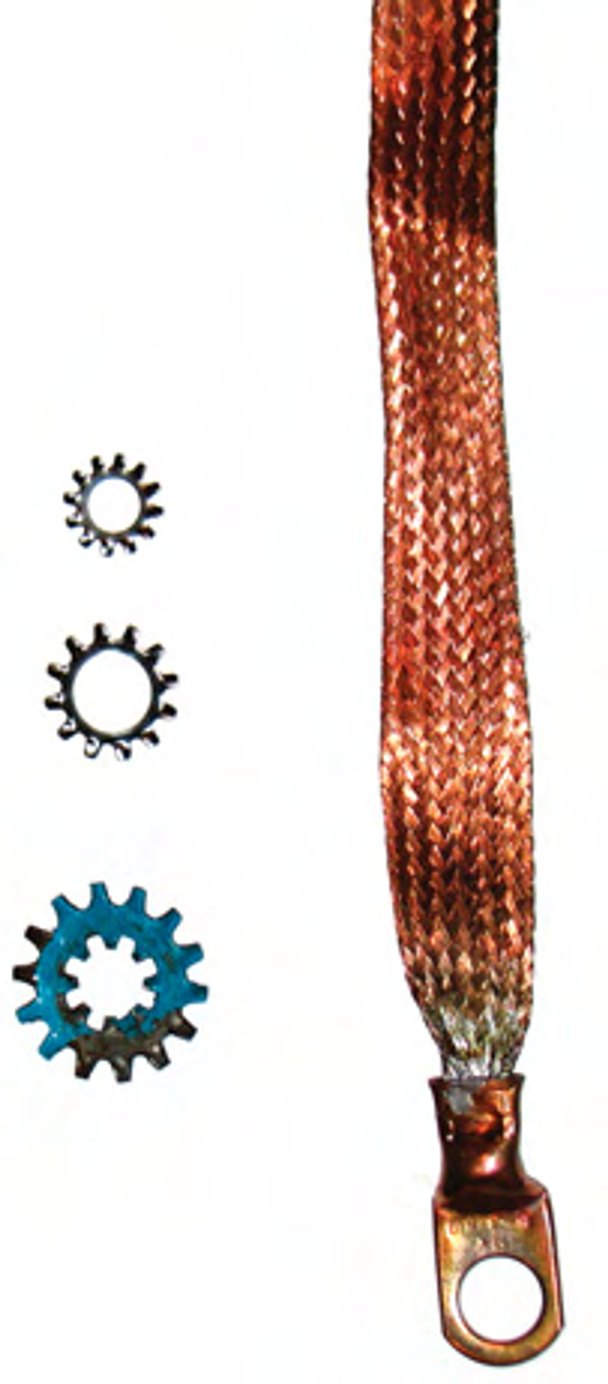
Measuring the electrical ground is actually quite simple. Note: this procedure is written for a negative ground vehicle. If your car has positive ground, reverse the polarity from the instructions below. First, turn on all of the electrical loads (lights, heater fan, radio, wipers, etc). Connect the negative lead of your voltmeter to the negative battery terminal. Set the meter to the lowest DC voltage range, then touch the other lead to a clean spot on the engine and read the voltage. Repeat the measurements between the battery and the frame, then again with the body. If you have good grounds, the readings should be under 0.1 volts. The lower the readings, the better your ground plane is. If you get more than about 0.3 volts, there is a problem somewhere. Inspect all of the ground straps and connections. You can improve the grounds by disassembling the connection points and cleaning them with a Scotch Bright pad, fine sandpaper or steel wool. Then apply a thin coating of dielectric grease to both sides of the connection and reassemble. Installing a star washer between the ground points is another good method to improve grounding. Each of the points on the star washer provides a current path, which is a very good thing.
If your car doesn’t have good ground straps or they are missing or broken, they are simple to add. You can add an extra ground strap anywhere between the engine or transmission case and the frame or body. If stock appearance is important, ground straps can easily be hidden under the chassis. For Tri-Five Chevrolets equipped with an AM radio, the dealer installed three supplemental ground straps to improve the ground plane between the engine, body and frame to eliminate radio noise (Photo 11).
On Project 55, one of the first things I did was check out the electrical system. The ground cables were high-quality 00 gauge, but the engine-to-frame ground was not very good. The engine side of the ground strap had been connected to the exhaust manifold but heating and cooling cycles and surface rust caused resistance to build up. The fix was simple–I moved the ground strap to the back of the head and used a star washer between the head and the ground lug. Problem solved (Photo 12).
OK, now that we have a good ground plane to start from, it’s time to check out the grounds at the lights. We do that by back probing the light socket. On some cars you can access the socket from under the hood, but others require the headlight to be removed from the headlight bucket. Once you have access to the light socket, measure the voltage difference between the light socket and the battery. Again, the lower the voltage difference between the ground pin at the light and the battery, the better. If you get a high voltage reading, investigate the ground connection to the body. If you find corrosion, clean it up well, then reassemble using dielectric grease and a star washer. Why is the dielectric grease important? That is what keeps the corrosion from coming back. If you have cleaned the connections and you still can’t get a good measurement, you can run a new ground wire and take it to a better ground source closer to the battery or engine block. You need to use the factory wire gauge, or preferably bigger (smaller gauge number). The longer the wire run, or the higher the bulb wattage, the bigger the wire diameter needs to be for both the power source and the ground wire. A 12-gauge wire works well.
Other Grounding Issues: Bad electrical grounds can cause a number of strange “gremlin” behaviors. Electrons are very sneaky, and will find their way back to ground any way they can. Here are a few of the interesting situations I have run into over the years.
Taillights require a proper ground to work like they are supposed to perform. Have you ever seen a car (with a dual-filament taillight bulb), where one taillight is half as bright as the other, and the light goes out whenever the brake lights are applied? That means that taillight bulb or socket has lost its ground. The defective side taillight works (at half intensity) because electrons are finding their way back to ground through the brake light filament on the other side of the car. When the brakes are applied, that grounding path goes away and the light no longer works. A friend had a truck where the backup lights flashed every time he used his left turn signal, and came on every time he stepped on the brakes. The left taillight housing had come loose from the body, so the taillights were grounding through the backup light circuit. The solution was as simple as reinstalling the left taillight to restore the ground path.
Years ago I worked on a car that had many strange dash symptoms: things that were supposed to blink didn’t, things that were not supposed to blink did, several of the gauges had a mind of their own, and the high beam indicator worked opposite of how it was supposed to. The owner did not know whether to call a mechanic or an exorcist! I noticed that turning the dash lights on caused erratic behavior on many indicator lights and gauges. I carefully pulled the dash cluster loose, and measured the power and ground to the dash lights and instruments, and discovered that the lights and instrument cluster had completely lost their ground path. The problem was a broken line somewhere in the printed circuit board of the instrument cluster. There was no practical way to fix the circuit board, but the solution was to add a new ground strap with 14-gauge wire between the instrument cluster and the body. Restoring the ground resolved all of these unusual problems.
All About Relays
Electrical relays are another popular topic among AR readers. Reader Kenneth Hawkins writes: If you really want to maximize the output of your upgrade, the stock wiring should get as much attention as the source. Mr. Harlan mentions relays in passing, but these are a must if you are serious about illumination. No point putting in a great bulb, if the long runs of tiny wires in the stock harness have so much resistance that the voltage to the lights is significantly reduced. For a great Web site discussing this and other lighting upgrade issues, see http://www.danielsternlighting.com /tech/tech.html.
Reader Ray Guarino adds: Installing an inexpensive relay in a lighting circuit delivers full power to the device, prevents aged wiring from heating up, and most importantly they change the way the current is routed to the lights. In all the cars we’re familiar with up to the 1980s the manufacturers used the headlight switch as an active component in the wiring path between the battery and the lights meaning all the current that is pulled by the lights had to travel through the switch. Relay usage changes the way the current is delivered, using the switch as a low-voltage trigger to activate the separately powered load terminal of the relay which powers the lights. As a result, less wiring carries the current load, devices are taxed less, and voltage drop decreases resulting in much brighter lights.
I installed relays in my 1979 Fiat Spider last year and saw a great benefit as a result. When I turned on the headlights in their stock configuration Isaw a 4-volt drop as measured at the back-probed light socket (with the light on). Once the relays were installed the drop at the lights lessened to within one volt andthe voltmeter mounted in the car remained rock steady.
I purchased new Bosch relays for about $2 apiece and wired sockets for around $3 each at a local swap meet. I already had the few feet of colored wire needed to complete the new circuit paths, but if needed the wire also can be bought at a swap meet at discount making the homemade version of this project a lot more affordable than packaged kits found on the Internet costing $25and up.
Mike’s Response: Ray and Kenneth are absolutely right—if you want to have a high-performance lighting system, you need to have good power to the bulbs, and relays are an effective way to get there. Some stock wiring systems work reasonably well to begin with,but others are inadequate and adding higher wattage bulbs only aggravates the problems.
The relay uses a low current electrical signal from the stock headlight and dimmer switches to control the lights, but the high current draw travels directly from the battery or alternator directly to the bulb. Relays offer some great advantages when powering high current draw electrical devices, such as headlights. Current-generation cars also use relays to power electric fuel pumps and fans. This allows much shorter wire runs with larger diameter wires, resulting in higher voltage to the bulbs, fans and pumps.
I have used relays on both daily drivers and project cars, and they are pretty effective. Note that relays come in several amperage ratings. Select the highest amperage your system is going to need, then add at least a 50% safety factor on that. For headlight applications, I use relays rated at double the current draw. The most common relays on the aftermarket are Bosch relays and GM waterproof relays. They are both good choices. If you do choose to use a headlight relay, be sure to put a spare in your emergency tool kit just in case.

Two relays are required—one for the low beams and one for the high beams. You’ll need to wire in the relays using a 12-gauge automotive grade wire tied in from the battery or alternator as a power source. Be sure to put a fuse (or fusible link)in this wire for safety, as close to the powersource as possible. Make sure you safely route and secure your new wires. Figure 1 shows a typical relay wiring schematic. I show two headlights for drawing clarity, but the wiring is similar for a four-headlight system.
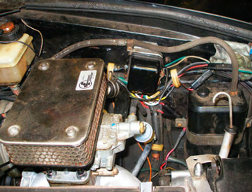
One of the biggest complaints about using relays in an old ride is the way they look. Ray Guarino came up with a very clever way of installing this modern technology into his’79 Fiat.Ray hid the headlight relays inside of an old gutted-out Delco voltage regulator. The regulator cover hides the relays and looks like it belongs there—a very clever idea. The voltmeter proved the results—Ray’s Fiat showed an increase of 2.7 volts at the bulb, which is very significant. Photos 13a and 13b show the camouflaged relays.
A “No” Vote for HID Lighting Conversions
Reader Kenneth Hawkins also wrote: I have appreciated the recent series of articles on upgrading the lighting in our vintage cars, but I must disagree with Mr. Harlan in Part 2 of the series (headlight upgrades). Although it is possible to buy kits that allow you to convert non-sealed halogens to HID (high-intensity discharge) sources, this is a very bad idea. The spatial distribution of light intensity that results from a halogen bulb filament and an HID arc are very different. The optics of the halogen housing have been designed to focus halogen bulbs. Placing an HID bulb in that housing results in a lot of light going where it doesn’t belong…mostly in the eyes of oncoming drivers. Also, although HIDs appear much brighter, that is mostly because the human eye has fewer blue light receptors, and so they are overwhelmed. This also means the eye does not see with as much spatial resolution in the blue. So while you may be illuminating more with an HID, you actually “see” less, and the conversion kits are illuminating things you don’t need to see at all.
Mike’s response: Thanks for the letter and for the information, Kenneth. You bring up some great points and, in fact, we agree on many things. In the article, I stated “As of this writing,I am unaware of any available sealed beam conversion kits that use HID lights. If you really have your heart set on HID lights in your vintage ride, it can be done in two steps. First you have to convert from sealed beam lights to Halogen, and then use a conversion kit to switch the bulbs from halogen to Xenon. Of course that takes a lot of money and work.” I should have added one more sentence: “But I personally would not.”

I have continued to do research on these conversions, and several automotive experts pretty much agree with what Kenneth issaying—HID conversions are not a good idea. They don’t work properly because they require different optics than halogen lighting. It is like wearing your brother-in-law’s glasses—you can see, but you can’t see properly because the optics are wrong. There are a lot of Halogen-to-HID conversion kits on the market, and quite a number of late model cars have been converted to HID lights in place of the stock halogen bulbs, but that doesn’t make it a good idea. It is true that they put out a lot of light in the foreground, but other drivers complain about the glare from them and there are questions about how well they work for distance vision. I have also been reading reports of reliability problems with some of the kits.
Based on these issues, I agree with Ken that converting sealed beam headlights to Halogen housings with HID bulbs is not only expensive, but is probably not wise with the products that are currently on the market. Let me revise whatIsaidintheMarch article. “While it is possible to convert to HID lights in your vintage ride, this is not a good way to go. You are better off keeping with halogen lights until a manufacturer develops an effective, properly designed HID replacement for sealed beam headlights.”
More on Those Troublesome Thermal Cutouts
Reader Gary Tayman writes: I read with interest your article on headlight upgrades in the March issue. I would like to make a comment or two, as I have had my share of headlight problems with my 1964 Thunderbird.
First off, the 35-watt sealed-beam halogens mentioned are an improvement, not mainly because of brighter lights, but because their higher efficiency allows for less current draw. The DOT specs for the low beams are that they provide about the same light, but draw less current. This is why you can upgrade to these lights in an older car, but never use conventional lights in a new car because the wiring is not approved for the current. High beams provide more light than with conventional sealed-beams, without increasing the current burden.
But the biggest point of interest here is with the switch. Headlight switches, for safety reasons, have thermal contacts in them. Should there be an overcurrent, the contacts will heat up and open. Sure, the lights will go out, but will come back on again—flashing in Christmas-tree style to allow you to see the road well enough to pull over safely. Unfortunately, the contacts are much more failure-prone than the rest of the circuit! I can’t count the number of people who have told me to bypass the switch with a relay, and I’m sure the lights will work, but you lose that safety feature when you do. I’ve not done this; in my case, halogens improved but did not fix the problem. I eventually found an NOS switch.
However, the article author came up with a “Why didn’t I think of that?” solution: bypass the thermal contacts with a fuse!In his instance he installed a 15-amp fuse and cut out the contacts. I think it might be better to leave the switch intact, and bypass the contacts with a smaller fuse, maybe a 7 amp. In normal operation the current will be shared by the contacts and the fuse. If there’s an overcurrent, the contacts will still heat up and open. OR, the fuse will blow first. Either way, the safety contacts will take over, flashing the lights as they were designed to do. This Is much easier than installing a relay, and you retain the safety of the circuit.
Mike’s response: Thanks for sharing your experiences, Gary. I am glad you were able to find an NOS switch to get your ’Bird back on the road. Those kinds of issues can be pretty frustrating. I do like the idea of using a smaller fuse, creating a “parallel path” for the electricity to flow to the headlights. I thought of that too, but ultimately I did not go that route. My concern is that the current will certainly not be split evenly between the thermal cutout and the fuse, so trying to find the right balance of fuse size vs. thermal cutout would require some experimentation and a bit of guessing. If the thermal switch did open for any reason, the current spike would almost certainly blow the fuse, going right back to square one. I am pretty sure that with a bit of “on the road engineering” a guy could come up with the optimal combination of a fuse along with the thermal cutout to make the system operate reliably. In my case I wanted a “one and done” solution that was guaranteed to fix the problem once and for all. So far so good!
Paint It White!
Reader Thomas Behnke writes: A suggestion on the reflecting of the light: forget the aluminum foil and silver paint—use BRIGHT WHITE. It is many times better than silver.
Mike’s response: I have never tried this, but it makes perfect sense, since white paint absorbs the least amount of light. I will try white the next time an opportunity presents itself. Thanks for the great suggestion!
Proper Wiring of a Third Brake Light
Reader Ed Armatys writes: There was an article in the February issue which caught my attention and I thought that I should try to clarify some things for fellow hobbyists. On pages 24 and 25, for example: The addition of a third brake light to an older vehicle is a great idea. However, wiring the third light into a wire found in the trunk will also make the light flash with the turn signal that it is connected to, right or left. The wires found in the trunk are separated by right and left turn/stop circuits. The only way you can get a “stop only” circuit is to connect the third light to the brake switch circuit wire that is going from the brake switch to the turn signal switch in the column. This Is where it is separated into right and left circuits.
The Chevy shown should connect the third stoplight to the white wire going from the stop light switch at the brake pedal to the turn signal column switch. The purple wire in the trunk is only for the right stop/turn light, and the pink wire in the trunk is only for the left stop/turn light.
Mike’s response: Thanks for writing, Ed. You are absolutely correct on all points, including the wire colors. In fact, this is exactly the way we wired the ’55 Bel Air in the article. On cars with integrated turn signals, there are no wires available in the trunk that can be connected directly to a conventional third brake light unit that will make the light come on with the brakes and not blink with the turn signals.
The February article states: “Next I strung a new wire directly from the brake light switch alongside the wiring harness to the trunk, connecting to the third brake light unit.”
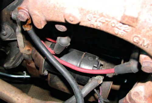
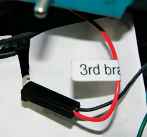
Let me add a few more details about exactly how this was done. I started by connecting a long wire directly to the output of the brake light switch (in my case I used a red 18-gauge wire). On early Chevys, the brake light switch plugs into the wiring harness using a male spade terminal, so I cut off the existing spade terminal from the brake light switch and installed a new spade terminal over both the switch wire and the new third brake light wire (Photo 14). Next I carefully routed from under the dash to the third brake light in the trunk. I ran the wire alongside the factory wire bundle, and used plastic wire ties to hold it tight to the main wire harness. I am a big believer in labeling wires for future maintenance, so I added three labels: one under the dash, one halfway back, below the driver’s door sill plate, and in the trunk. This allows the third brake light to come on any time the brake pedal is pressed, but does not blink when the turn signals are used.
There are some third brake light units on the market that have two elements— one that duplicates the left and right taillights. These units are wired directly from each taillight unit. I have never used one due to personal preference, but they are still a great safety improvement and are easier to wire because all connections are available in the trunk.
Light Sources
Many readers have written in asking where to get lights like we used in the articles. Here are several sources for lighting upgrades:
Headlights: I bought my halogen headlamps from a local (Seattle area) store, but they are available online from a number of sources. Here are a few:
Eckler's Classic Chevy (classicchevy.com)
Streetside auto (streetsideauto.com)
Aardvark International (www.talbotco.com)
JC Whitney (jcwhitney.com)
Speedway motors (speedwaymotors.com)
Many of the street rod shops also carry them, either the tri-bar or the OEM style.
The premium headlight brands are Cibie, Marchel, Hella, and Delta Tech. I have personal experience with Cibie and Hella, and like them both. I have a set of Tri-Bar headlights from Speedway Motors for an upcoming project and they look like quality parts. Tri-bar headlights look pretty different from an OEM application, but are often used on street rods and customs.
Halogen Taillights (with 15/50 watt elements):
Eckler's Classic Chevy: (classicchevy.com)
Speedway motors (speedwaymotors.com)
Third brake lights:
Speedway motors (speedwaymotors.com)
Juliano's Hot Rod Parts (julianos.com)