How -to Restoring Car Seats, Pt. 2
It’s Time to Tackle That Failing Power Seat Mechanism. Unfortunately,It’s Not Meant to be Repaired.
Editor’s note: We started this project by adding new foam to the Chevy Caprice Classic’s compressed front seats and now we’ll take a look at a power seat mechanism that has begun to fail. There were 12 photos with last month’s installment so we’ll pick up here with Photo 13.
THE NEXT STEP in this project is to explore the driver’s side power seat problem.
The motor works, but the seat will only move forward. This was a progressive situation. It started as intermittent operation with certain switch movements and ended up operating only in the horizontal mode, going forward.
Components to Consider
This six-way power seat system has the following components that may need to be considered when diagnosing problems:
1. Fuse (had there been no motor activity).
2. Switch (control) mechanism.
3. Wiring harness connecting the switch with the motor assembly.
4. Motor coupled with a three-solenoid transmission.
5. Drive cables (six).
6. Adjusters—two front and two rear for vertical movement, and two for horizontal movement.
Let’s Look at the Motor and Transmission Assembly
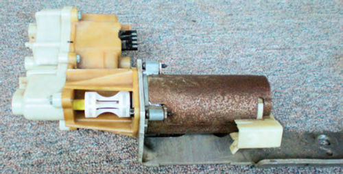
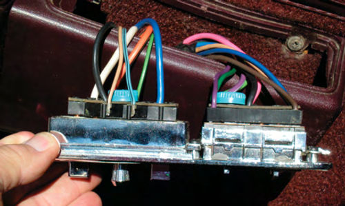
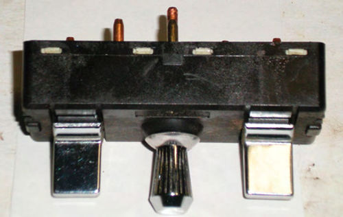
I normally would start by checking the control switch, but seeing as the seat was removed for the cushion work and is conveniently out of the vehicle, let’s start with a quick visual inspection of the motor assembly. Photo 13 shows the motor united with the transmission and still completely connected to the seat. There is only one solid mounting point: A stud located atop the front of the left seat rail. Thatsecuresthe bracket which is sandwiched in between the motor and transmission assembly. There are a total of six cables, three on each side. The forward most pair controls the front vertical movement; the central pair controls the rear vertical; and the rear pair (you can see the red one in the photo) controls the horizontal. These cables simply push into the transmission; much like a speedometer cable would fit into a vehicle’s transmission. There is a retaining plate on each side that holds them in place with two screws attaching to the transmission.
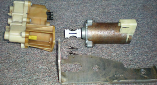
In Photo 14 the assembly is removed. Note that there are two electrical connectors, one on the motor and another for the transmission. The motor will receive a voltage signal whenever a switch is activated, and polarity will reverse when the switch’s direction is changed.
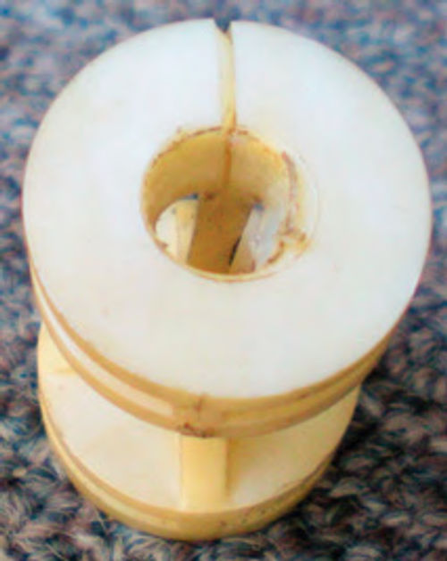
In Photo 15 the motor, transmission and bracket are all separated. Notice that on the end of the motor’s shaft there remains a white plastic coupler that connects it to the transmission. This simply slides onto each shaft, and it’s designed to absorb some of the shock each time the motor starts and stops. Upon closer inspection a crack was discovered in the coupler which would allow it to slip when the motor was activated. (Photo 16 gives a clear view of it.) This part could be fabricated if needed, but my first thought was to contact a local Chevrolet dealer and determine the part’s status. For anyone who might be interested, the GM part number is 20614175. Unfortunately, it’s no longer in production, but they did a computer search and found one remaining on the shelf at a Buick dealership about 70 miles away. A phone call and credit card got it on its way. During my conversation with the Buick parts clerk he mentioned this was a very common item to fail in its day, saying something like, “we sold thousands of them.”
Normally the entire assembly wouldn’t have been removed to replace this part; the transmission would be left in place. This was simply done to give readers a better view of things, and what to expect if the transmission needed to be removed.
Now to the Switch and Wiring
The next step is to check the control switch and verify that a signal is being sent through the wiring harness to the motor and transmission. In this vehicle, the switch assembly is positioned on the top of the driver’s armrest.While very well sealed, dust and dirt sometimes can manage to filter their way in over the years, so this could be a possible problem.
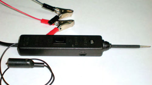
Each switch will be individually pushed in one direction and then the opposite way. With a Power Probe (or test light) the connector plug that protrudes through the floor’s carpet will be probed for voltage signals. If you’re not familiar with a Power Probe tool, take a look at Photo 17. It’s a sophisticated test light that can verify both positive and negative signals as well as supply both for testing purposes. It’s connected directly to the battery (in most cases), and when a connection is probed, its indicator will light Green for negative or Red for positive. By using its rocker switch, positive or negative signals can be supplied to the probe’s tip for testing. The small alligator clip seen in the photo can be used to supply the ground connection. The advantage of the Power Probe in this situation is its ability to quickly identify both positive and negative connections. The readings will then be recorded.
Making a Switch Response Chart
Take a look at the “Power Seat Switch Response Chart” on page 21. It shows each possible switch position and each wire’s color. The Black wire to both the switch and motor is always negative, so for simplicity it was not included in the chart. The response for each wire is noted as positive or negative. This is a simple test, and at this point all we are looking for is a “change” in the voltage pattern. In other words, each switch movement should send a different signal, and when that same switch is tilted in the opposite direction, the voltage pattern should again change. As long as a different signal is observed for each switch movement then the switch mechanism and wiring are likely not the problem.
Pay attention to the wiring harness connector on the switch seen in Photo 18. While unlikely, a loose or corroded terminal can act the same as a bad switch, so make sure the connections are good.
During the test a flickering positive voltage signal to the large blue motor wire was noted in both the “rear vertical left” (RVL) and the “center knob rearward” (CKR) positions.
My first thought was to try something easy. In Photo 19 low-pressure compressed air was applied while working the switch in an attempt to dislodge any debris that might be causing the problem. Unfortunately, that didn’t help, so the next step was to try flushing it with a solvent like Naphtha.
Caution, always do a testfirst. Apply a tiny amount of the cleaner/solvent to an area that won’t be visible. If there appears to be more than one type of plastic, apply it to all of them. Wait a minute and make sure that the plastic remains unaffected.
Skipping thistest and simply spraying the switch could leave you with a soft, gooey switch that will have to be replaced. If you have any uncertainty, don’t attempt to flush the switch!
I chose to use Naphtha because it’s safe on most plastics, but always do a test anyway. Again it was followed with low-pressure compressed air to help carry and evaporate the solvent…but still no luck.
Should We Replace or Repair?
The options have now been reduced to replacing the switch (if one can be found), or attempting to take it apart and repair it. The thought of getting a used switch from a salvage yard is unappealing. It’s not that I don’t enjoy hunting around in the old “bone yards,” I’m just concerned about ending up with another switch with the same or similar problems. Upon contacting Chevrolet about a replacement power seat switch (the GM part number is 20411768) they advised that it was no longer manufactured. They were, however, able to locate two dealers in a neighboring state that had the part in stock. One dealership wouldn’t take any phone orders or ship items, but the second was glad to help, probably happy to move the old stock. The new switch was purchased, (the cost was much less than I had guessed, $40 plus freight) but I still couldn’t resist attempting to rebuild the old switch anyway. After all, it would probably take a week before the new one arrived, and if successful, I would simply add the new switch to my own “award winning” parts department.
Having a new switch is an added bonus in the event there is a failure in the plastic control levers. Those would be difficult to repair. Besides, the knowledge gained in cleaning and adjusting this switch can be applied elsewhere in the future. So, the decision was made to see if it could be repaired. The problem simply may be a buildup of dirt in the switches, or something a bit more complicated such as corroded contacts or even broken parts inside. This is new territory for me, and I fully expected springs to try and pop out.
The best approach is to proceed slowly, and if one’s available, use a digital camera to record each step.
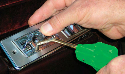
First, the switch needs to be removed. The screw that secured the switch panel to the armrest had already been removed and a little wiggling was all that was required to free the switch panel. Again, refer back to Photo 18; it shows the wiring harness still connected. The blue colored cap in the center is what secures it, and rotating it counterclockwise removes it. The harness simply pushes on, but it’s a snug fit. Use a miniature screwdriver to pry the harness from the switch. Proceed around the perimeter prying gently and equally. Finally, there were two screws that retain the switch to the switch panel.
These switches were never meant to be opened and serviced, so there are no screws holding it together. After a quick examination, tabs were discovered that secure the switch to the exterior chrome plastic shell. Prying the shell open slightly exposes one of them as seen in Photo 20. There are a total of four tabs, one centered on each side. There is some flex in the plastic, but not enough to allow the switch to be removed. I decided to remove the tabs with a miniature hobby knife as seen in Photo 21. The plastic is soft, and the tabs cut off easily. Note also in the photo the black indexing mark near the tip of the blade. This is to avoid the possibility of putting the switch back into the shell backward when it comes time to reassemble. Always make assembly reference marks. It only takes a second, and can save a lot of grief.
A word to the wise, don’t pull on any of the connection pins (like I did) when trying to separate the switch from the outer shell. I had thought the pins would be solidly anchored like a rivet to the switch; I was wrong. One of the pins pulled cleanly from the switch, so now more work has been created. It’s not the end of the world; the pin can be soldered back in position without too much trouble. This will be addressed later if the switch has been determined to be salvageable.
Some Useful Vocabulary
To avoid any confusion, here are a few terms that I felt best described some of the components inside the switch. (I would have used whatever vocabulary Chevrolet referenced in the service manual, but the switch is considered non-serviceable, so there was none.)
Plastic control levers. These are the levers you would move with your fingertips. This includes the plastic portion inside the switch as well.
Contacts. The point in the switch where the electrical connection is opened or closed, much like the vehicle’s ignition points.
Switch levers. Copper levers that are connected to one or more contacts. These directly control the circuits.
Rockers. These are two elongated “U”-shaped plastic bars that run the entire length of the switch. They link together and pivot back and forth in the switch working two switch levers on either side.
Disassembly, Cleaning and Tests
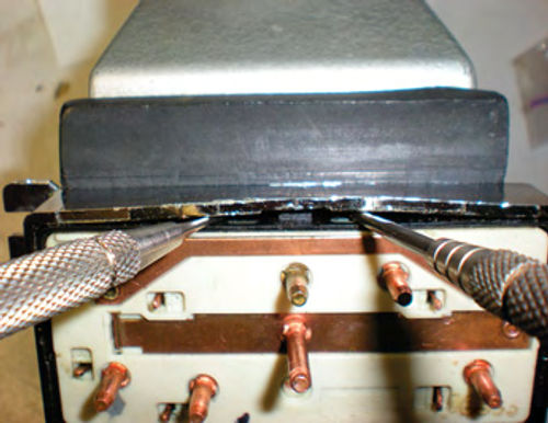
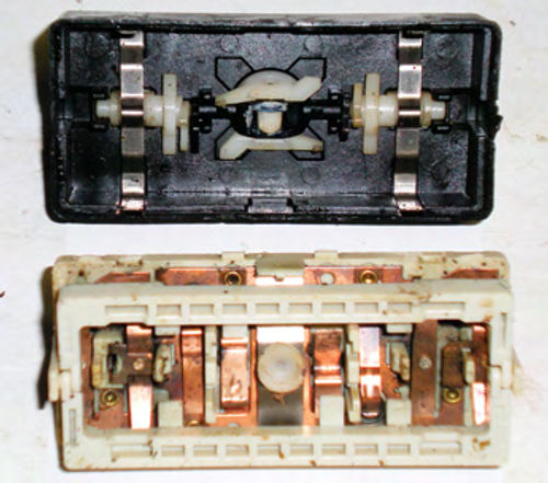
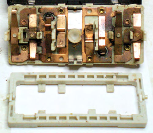
Once the tabs were removed, the switch was then pried out of its chrome shell and Photo 22 shows the results. Wow, for some reason I didn’t feel much closer to my goal of getting inside the switch. There are four white tabs on each side that lock into the black outer shell. This shell is thin and more flexible than the chrome one, but I still found it necessary to trim down the end tabs. Spreading open the black outer shell and persistently prying, it finally separated. Visible in the top of Photo 23 is the inside of the shell with the plastic control levers intact, while below it you see the electrical portion of the switch. There are three springs(“clips”) used in this switch, and none came popping out. Two can be seen inside the black shell at either end while the third remained with the lower portion of the switch, located in the center.
The plastic control levers must be inspected for damage, breakage or obvious wear. Had a portion of a lever broken off, it would be trapped inside the switch, thus emphasizing the importance of performing thisservice over an uncluttered, relatively clean work area. If a small, broken part falls out, you will find it, verifying that there is, indeed, damage.
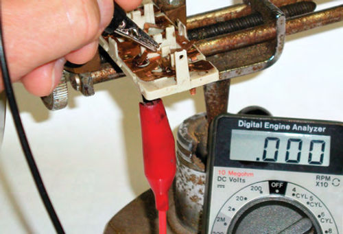
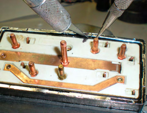
Photo 24 gives a clearer view of the contacts and switch levers with the “rockers” removed. The initial inspection doesn’t reveal any broken pieces so the next step is to get a look at the contacts themselves. A protective coating was used to prevent corrosion on the contact points, so that will need to be removed.
As mentioned earlier, use caution with cleaners. The copper certainly won’t be affected, but make sure to do a test on the plastic foundation.
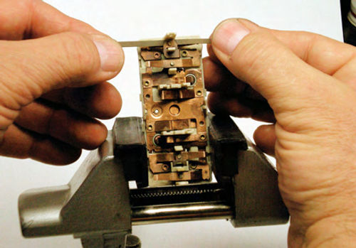
There was only one type of plastic, so I chose a more aggressive cleaner, LPS (brand) Contact Cleaner. Once flushed, the switch was blown dry with low-pressure compressed air. With the contacts now clean, it is much easier to inspect their condition. Minor pitting is to be expected. Contacts that are badly burned will require a more aggressive reconditioning, or possibly may be beyond simple repair. Nothing abnormal was found here, so 400-grit sandpaper was chosen to polish the contacts. Using scissors, a bunch of strips were cut about 2” in length. Some were 1/8” wide but most were 1/16” in width. Several passes were made with the abrasive between the contacts as shown in Photo 25. Using a hobby vise with soft jaws is helpful in holding the switch while you pull the abrasive between the contacts. Start with the abrasive facing one way, make several passes and then reverse it. When possible, squeeze the contacts together, applying light pressure as the abrasive passes through. Note that some switches have multiple contacts. This assembly has a total of 10 circuits controlled by eight switch levers. When cleaning or polishing the contact points, be careful to avoid bending any of these levers. This could change the balance within and make the switch work intermittently (or not at all).
Once the polishing was completed, the switch was blown off and flushed again with cleaner to remove residual abrasive. It’s possible that some minor adjusting (bending) of switch levers may be required. In most cases, this would be due to worn contact points or worn plastic control levers. Polishing the contact points will ever so slightly increase the air gap which could require some very slight adjustment. Unless there is something obviously askew, the best approach is to leave things as they are for the initial reassembly and test. The switch is not difficult to reopen if adjustments are needed.
Unfortunately, it’s impossible to see how the plastic control levers are interacting with the switch levers once it’s assembled. So, a good pre assembly test is to use an ohmmeter (or a 12V power supply with a test light) and verify the contacts are all working properly. In Photo 26 one lead is applying very light downward pressure on the switch lever, completing the circuit, while the other lead is connected to the corresponding terminal/pin. Continuity should be observed. If the corresponding terminal can’t be easily identified for a particular switch, simply make the connections on either side of the contacts, and verify its function. If light pressure closing a switch completes the connection, that’s what you are looking for.
Next: We’ll continue working with the power seat mechanism.