How -to Restoring Car Seats, Pt. 3
It’s Time to Reassemble and Test the Power Seat Mechanism. Then We’ll Tally Expenses and Review the Work.
EDITOR’S NOTE: IN the first installment of this series we added new foam to a Chevy Caprice Classic’s compressed front seats and last month we started working with a power seat mechanism that was failing. We’ll continue with the power mechanism this month. There were 26 photos in the first two installments, so we’ll pick up here with Photo 27.
Time to Repair the Pin I Broke Off
All appears to be in order with the seat mechanism, so now it’s time to solder the pin back in place that I pulled loose earlier. Cleaning and polishing up the mating surfaces of both the pin and copper grid are the first tasks. Next, using a soldering gun and rosin core solder both surfaces were “tinned” with a small coat- ing of solder, then the pin was slid back in position. Again with solder and soldering gun in hand, the copper grid is heated. Make certain to establish a good solder connection. It will take a bit of heat, so don’t stop too soon. You can tell when the solder flows together, it will typically “flatten” out as can be seen top center in Photo 27.
Finally, to protect the clean contacts, a coating of “KOPR-SHIELD,” a conductive, anti-corrosion compound manufactured by Thomas & Betts was applied. This was purchased many years ago through East- wood Co., but could likely be found at an electrical supply outlet and is available online for about $30 for an 8 oz. bottle. A toothpick was used to apply the pasty substance to each set of contacts.
Before continuing, check to see that the switch is free of any lint, hair or other stuff that doesn’t belong in there. Now it’s time to put both the plastic rocker bars in place, and slide the shell with the control levers back over it. Finally, make certain the two sections are completely seated together or the control levers won’t function properly. This one made an audible snap when the tabs locked in place.
One Final Test

Before leaving the workbench I decided to test the switch again now that it was reassembled. To make life easier a Sharpie was used to mark and identify each pin with its corresponding wire color. The switch response chart made earlier would now serve as a road map for testing. For example, the chart indicates that previously there was battery positive to both the Green and Large Blue wires in the Front Vertical Left (FVL) position. So one ohmmeter lead was connected to the pin for the Orange wire (Battery Positive supply), and the other lead was used to probe the other pins. Continuity should be indicated when either the Green or Large Blue pin connections are touched. The test is then repeated with one lead connected to the pin for the Black wire (Battery Negative/Ground). With the switch in the same position there should be continuity between it and the Large White wire.
Unfortunately, there was still an intermittent signal in one of the tests. I discovered that slight downward pressure on the switch while testing eliminated the problem each time. This may be an indication of slight wear in the plastic control levers, or the contacts themselves. When it was inspected, no noticeable wear or damage was evident, so some slight adjusting of a switch lever should solve the problem. This is nothing to be alarmed about. When there are two interacting components that can’t be viewed once assembled, this is always a possibility. It may take several attempts before all is 100%, so be patient.
Identifying the Wiring
At this point we should take a look at each wire’s function. This isn’t a difficult task. The Power Probe, shown last month in Part 2 of the series, identified both the Orange/positive and Black/negative connections at the switch, and the remainder of the wiring was identified visually by wire color and what they were connected to. The two wires connected to the motor are obvious. They will always indicate positive and negative polarity when a switch is activated, and their polarity reverses when that switch is moved to the opposite direction. Reversing polarity will reverse the motor’s direction of rotation. Typically, these also will be made of heavier gauge wire.
The function of a wire connected to a transmission solenoid can be identified by following the drive cables from that solenoid to see what adjusters they move. There are seven wires in the connecting harness at the switch.
1. Orange = Battery Positive supply to the switch, always on.
2. Black = Battery Negative (Ground).
3. Blue (heavy gauge) = to motor.
4. White (heavy gauge) = to motor.
5. Green = (to transmission) activates the forward most solenoid for the front vertical adjustments.
6. Brown = (to transmission) activates the middle solenoid for the rear vertical movements.
7. Blue/black = (to transmission) activates the rear solenoid, this is for horizontal movement.
Some Minor Adjustments Required


The problem mentioned above was with the “Rear Vertical Left” (RVL). The positive signal to the Large Blue (motor) wire would flicker. With the switch once again reopened I took a moment to study the contact levers and quickly realized that the plastic “rockers” (that were shown removed in Photo 24 last month) control the signals to the motor. Photo 28 is a side view of the switch; the red arrows point out two of the levers in con- tact with the rockers. There are a total of four levers, two on each side located near each end. Both the levers controlled by the left rocker have dual circuits with upper and lower contacts. This allows for the change of polarity to the motor. For example, in the “Rear Vertical Right” (RVR) position the right rocker presses down on two switch levers, while the dual circuit levers (on the left side) remain closed with their top contacts. This sends a negative signal to the motor through the Large Blue wire completing the ground connection. However, in the “RVL” position this ground connection to the Large Blue wire is immediately opened when the left rocker is depressed. Once completely depressed, the switch levers close with their lower contacts and a positive signal is now sent to the motor’s Large Blue wire reversing its direction. Don’t explode your brain thinking about this; just be aware that if adjustments need to be made to either of the dual circuit levers (as in my situation), it could disrupt their function in the opposite direction. So make notes indicating what lever you have bent, and do so minimally.
The focus in this case is on the switch lever that signals the Large Blue wire, in the “RVL” position. Identifying which switch lever controls this circuit is simple. Reconnect the ohmmeter (or 12V power supply and test light) to both the Orange wire pin (battery positive supply), and the Large Blue wire pin. Work each lever individually with your fingertip closing the contacts. When a response is noticed, you’ve identified the lever. Making the slightest bend in the switch lever to apply a bit more pressure to close the lower contacts was the goal. I didn’t keep track, but it probably took six attempts before all was working as it should. Make sure to recheck all the functions, not just the one being adjusted. The last thing you want to find is that something was missed, everything is back together, and there is a problem in another circuit.

Back to the Vehicle
Now that the switch had passed the final bench test, it was reconnected to the vehicle’s wiring harness for further testing. The seat’s motor assembly was still removed and easy to hook up, so it was plugged into the harness as seen in Photo 29. All functions were responding, so it was time to start putting things back together. There was no rush to put the seat switch back into its “chrome” shell. That would be the last task after all was confirmed to be working properly.
The next step is to replace the seat motor and transmission assembly. As previously mentioned, removal wasn’t required for any of the services that have been performed. This was only done to give a better view of things, as well as what to expect if the transmission had needed to be removed. All of that being said, if it’s not necessary to remove it, don’t.
Synchronizing the Drive Cables
If there weren’t any questions with regard to the drive cables being properly synchronized, and none had been rotated while the assembly was out, it’s just a matter of plugging the cables back in; securing each side’s retaining bracket, and then the mounting bracket would be reconnected to the stud on top of the left seat rail. If there’s any uncertainty, take the time to make sure the cables are all synchronized.
Here is the method as described in the Chevrolet service manual with the motor installed:
“Horizontal travel—operate seat control switch until one adjuster reaches full- forward position. Detach horizontal drive cable from adjuster which has reached full- forward position. Operate seat forward until other adjuster reaches full-forward position; then connect horizontal drive cable and check horizontal travel of seat.”
“Front or rear vertical travel—Operate seat control switch until one adjuster has reached fully raised position at both front and rear vertical travel limits. Disconnect both front and rear vertical drive cables from adjuster which has reached the fully raised position. Operate seat control switch until other adjuster reaches the fully raised position at both front and rear vertical travel limits; then connect previously removed front and rear vertical drive cables. Check vertical travel by operating adjusters through one or two complete cycles. The above operation may be repeated on an as-required basis if adjusters do not appear to be in phase after test cycle.”
With the Caprice, the motor and trans- mission assembly were not installed in the seat, so these adjustments were per- formed by rotating the cables by hand. The horizontal cables were adjusted full forward, while the vertical were fully raised at both front and rear. A small tap holder is perfect for rotating the cables as shown in Photo 30. A battery-powered drill also can be chucked to a cable to move more quickly through the range as seen in Photo 31.
Once the drive cables are positioned properly, the transmission can be reconnected and all secured.
The final test required that the seat be temporarily placed in the vehicle and the harness reconnected. This is done without securing the seat to the floor. The driver’s seat was allowed to lie back against the rear seat giving a clear view underneath to verify the adjusters were all in phase. If it’s found that additional adjustments are necessary, disconnecting a cable from its adjuster might be easier than from the transmission depending on the cable. The cable ends that connect to the adjusters have a black boot that is somewhat flattened on opposite sides. Look closely in Photos 30 and 31; you will spot a couple of them. Squeezing it, making it more round will allow the cable to be disconnected.
All that remains is to fasten the short wiring harness to the seat frame. It’s held in place by a plastic push-in pin that’s secured with tape to the wiring.
The seat is now ready to be secured. Put on any trim pieces that have been removed. I found myself having to loosen the seat to put on a section of lower plastic trim that I thought would fit once it was in position. Finally the seat was repositioned on its studs, and with the harness connected, the seat was secured in place.
Now it was time to put the switch back into its chrome shell. Remember the tabs that had secured it were cut off in order to remove the switch. So while it fits up into the chrome shell perfectly, it wouldn’t stay there. Two options quickly came to mind. One was to simply secure it with the aid of some silicone adhesive placed around the perimeter of the switch before sliding it into the shell. Once cured, this would secure it to the chrome shell, creating a strong bond. Should the switch need to be accessed again in the future, the same hobby knife used to cut off the original tabs could be used to cut the silicone seal.
The second option was to secure the chrome shell to the switch with several short, tiny screws. The obvious advantage of this was the ease with which it could be taken apart if that were necessary. The concern was that the screws ultimately would anchor in the foundation of the switch mechanism which was only about 1/8” thick. After all the work that was put into repairing the switch, I certainly didn’t want to risk cracking and damaging it.
The decision was made to go with the silicone adhesive, thus not taking any chances. It was applied in a few spots around the perimeter as opposed to a continuous bead. This will be adequately strong once cured, and will make removal easier (if it should ever become necessary again). Once completely cured, the switch was secured to the control panel; the harness was reconnected and the blue cap replaced to secure it. The panel was tucked into the front edge of the armrest and the one retaining screw replaced. The job was finished.
A Review of Our Results
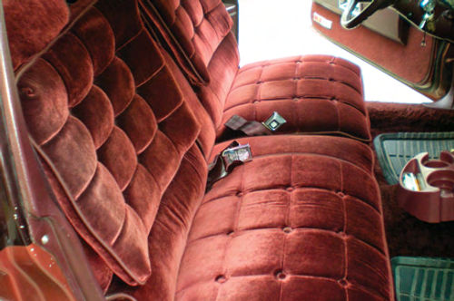
Photo 32 shows the final results of this multi-phase project. The seats are certainly fuller in appearance, but most importantly they are considerably more comfortable. While we were unable to repair the passenger’s seat manual reclining mechanism, full function was restored to the driver’s power seat.
The seat foam portion of this project moved along very well, but the power seat switch took a bit more time due to the trial and error testing method. The cost was minimal, totaling about $65 (not including the extra switch that was purchased). The foam was $50, while the motor coupling was $15.
If I were to do it all again the only thing that might go differently would be dealing with the armrest.
I recall reading that an electric carving knife will do a great job of cutting foam. This might have been the tool needed to taper the seat foam underneath the arm- rest. As it turned out, the armrest is a bit springy when it’s lowered against the seat cushion, but not so bad that it’s an issue. (Editor’s note: After reading the first installment in this series, two readers also suggested an electric carving knife for cutting the foam. See their letters on page 4.)
The power seat problem experienced in the Caprice was ultimately two separate issues. There was the broken coupler that allowed the motor to spin while not properly engaged with the transmission, and then there was the switch that was working intermittently allowing the user to sometimes hear an audible clunk with no seat movement.
Keep These Sources in Mind…
During my initial parts hunting I was surprised to find Advance Auto Parts had a listing for the power seat switch through “Dorman Products” although they ultimately advised me it wasn’t currently available. However, Dorman did have quite a selection of items available for vehicles of this era. Power window switches were readily available for both the Caprice and my ’87 El Camino. Some were even in stock. Now this is not a cost- saving measure, there was no noticeable savings when compared to purchasing through Chevrolet. This is, however, another option to remember when you're trying to locate parts. (Advance Auto Parts: advanceautoparts.com; and Dorman Products: dorman-products.com.)