
Buying & Owning a Brake Lathe, Pt. 2
We’re Working With the Machines’ Adapters and an Arbor. We’ll Also Make a Replacement Lathe Lamp.
Editor’s note:Last month we bought three brake lathes,sold one of them and began to consider the sale of a second lathe. This month we’ll take a closer look at the lathe adapters and do some maintenance and repairs. Although Photo 6 was in last month’s installment, we’re running it again here because it’s mentioned in the text.
Inspecting the Adapters… and How They Are Used
The next task in our brake lathe project was to clean all the adapters and compare them. After all, I certainly wanted to retain the ones in the best condition for myself.The lightly rusted ones cleaned easily. That cleaning did discolor the finish, but there was no pitting. These adapter cones are hardened, and the finish is precisely ground. Ammco state sin its manual that should some minor nicks be discovered, they can be smoothed carefully with a stone. Things to look for are deep chips or nicks in the finish, as well as checking their fit on the arbor for excessive looseness. As it ended up, all the adapters stayed with the machine they came with when purchased.
Photo 6 shows the centering cones and various adapters that came with the Hustler(Ammco’s 7000 disc brake lathe). The top row consists of the cone centering spring and three hubless adapters. They would be used in conjunction with one of the centering cones shown in the middle row, and would be positioned on the arbor as seen in Photo 7. The rotor (or drum, depending on the machine) would be positioned on the centering cone, and sandwiched snugly between the hubless adapters. The bottom row shows the double-sided tapered cones used in most hub-type applications. A large and smaller cone is typically chosen to fit up against the bearing races and the arbor nut tightened to secure the rotor.
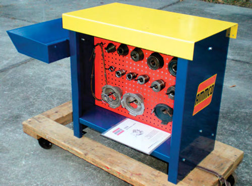
Photo 8 shows the Hustler’s freshly painted bench, with the chip tray in position, and the tool board loaded with the adapter cones. A free download of the lathe’s instructions and parts identification was printed, along with a page illustrating and showing the part numbers of a basic centering cone adapter kit. While there are many different adapters out there, the prospective buyer can see this illustration and have the confidence of knowing they at least have the basics to get started. Simple things like this can sometimes make the sale.
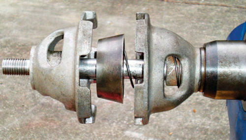
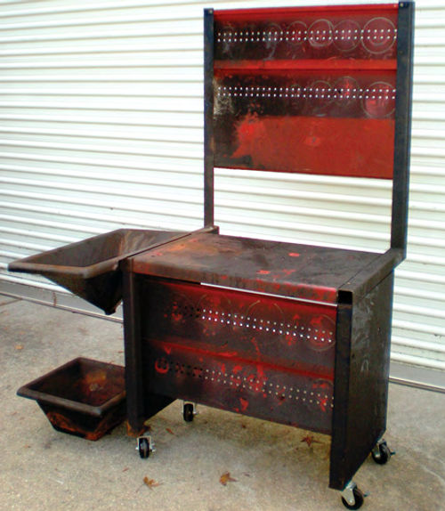
Photo 9 shows the bench for the Ammco 4000 (a combination lathe designed to handle both rotors and drums; the type of lathe I’ve really wanted). That bench was a mess! When compared to the modest bench that’s supporting the Hustler, you can see how much additional storage space there is for adapters. The casters you see under it were my temporary addition to make it easy to move around.
Also notice the different color scheme. Yellow, blue and red were used on the older Hustler lathe bench which dates back to the early 1970s. Underneath all that dirt in photo 9, this one is blue and red, a product of the mid-1980s. Their machine nameplate also changed over the years. The Hustler has a casting date of 4-71, and its nameplate has yellow, red and white backgrounds with black lettering. On the other hand, the 4000 (a 10-86 machine) has red and white backgrounds with black lettering as seen in Photo 5 last month. For the most part this is just interesting trivia, but if you are walking up to a machine you will have some idea of its era.
Adding Bench Casters Is More Than a Simple Bolt-On Project
The larger bench for the 4000 will occupy a space in the front corner of my garage near the bay door. This vacant spot has the advantage of allowing ambient light in when the door is raised. Unfortunately, the height of the upper tool board will block access to the garage’s electrical service panel. Because of this the machine and bench will need to be mobile.
While the bench is pictured on casters in Photo 9, that setup would be too flimsy. The holes that had been used in the photo were actually for anchoring the lathe bench to the shop floor, not for casters. Some heavy angle iron was purchased from the local scrap yard and welded together to form the frame seen in Photo 10. It was drilled and threaded so that the casters would line up with the existing holes in the lathe bench. The bench was completely disassembled, cleaned and painted just as the other had been. Other than this being a much larger bench, the process was the same. The bench was then set into the frame and secured to the studs protruding up from the casters.
Changing the Gearbox Grease
Most likely the gear box grease had never been changed in either machine. It’s a messy job as the drain plug is located flush on the face of the lathe, grease will come dribbling down the front of the machine, and would ultimately get trapped between it and the bench. So, getting that job out of the way before cleaning either lathe made sense.
Each machine was run for about 15 minutes to warm up the grease and get it moving around, then a 5/16” Allen wrench is used to remove the plug and drain the lathe. Photo 11 shows the Hustler’s drain plug located just below the smaller torn boot. And if you’re wondering, yes this photo was taken after the machine was cleaned and painted, so it’s easier to see. One pint of fresh 80-90 gear lube was poured into the gearbox through the fill cap on the top of each lathe. The cap has a dipstick for verifying the level. The next time the grease is due to be changed, a 1” long section of 3/8” NPT iron water pipe (or plastic equivalent) could be quickly threaded into the lathe once the plug is removed. This would make catching the draining grease easier, keeping the flow off the face of the machine.

Removing a Stuck Collar From the Hustler’s Arbor
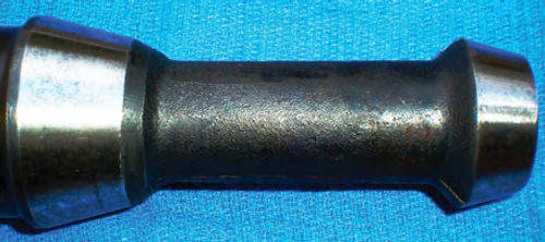
Photo 12 shows two things. The red arrows point to the scribe line on the neck of the machine and the small etch mark on the shoulder of the arbor. Ammco refers to this as the “witness mark.” This is where the relationship between the original arbor and machine were marked at the factory indicating its truest running location.
If the arbor is the original one that came with the machine from the factory, it will be engraved with the last three digits of the lathe’s serial number in between the two tapered mating surfaces that fit into the machine. To the right of the arrows is a 1 ⁄2” spacer collar that’s stuck up against the shoulder. It shouldn’t be there, and removing it is the next project.
If rotors have been machined with that collar stuck there, they most likely weren’t cut true. The adapter cone, or hub-less adapter must be placed directly against the large shoulder of the arbor. This small spacer is insufficient in diameter to properly support either, and there shouldn’t be a need for it there anyway.

This collar isn’t hardened, so a hose clamp was tightened around it to aid in grabbing it and avoid any additional chewing up of its OD. With a liberal amount of WD-40 applied,slip joint pliers were used to try and rotate the collar, but no luck, the clamp just slipped. Ultimately, the arbor was removed and secured in a vise with the shaft in a vertical position. The two tapered mating surfaces that fit into the lathe (Photo 13) were protected with thick layers of duct tape as well as the area in between them. It was secured with the jaws clamped to the rough cast area located between the two tapers. Any damage to either of these hardened mounting surfaces would be disastrous.

At this point I just wanted the collar removed, and lost my concern regarding how beautiful it would remain. Vise Grips were clamped onto it, and some slight rotation was obtained. With the arbor vertical, WD-40 was better able to penetrate between the spacer and the arbor. After almost an hour of patiently working the spacer back and forth while continually trying to pull it free, it started to move up the arbor until finally it was removed. During all this time I couldn’t help but wonder what the condition of the arbor would look like beneath it. Thankfully it was fine; there was no indication that anything had been stuck there. The collar must have gotten compressed slightly after being sandwiched there, creating an edge on it that made it resist removal.
Had these attempts failed, heating it with a torch or even cutting it off with a small abrasive wheel would have to be considered, both of which could be damaging to the arbor if I had not been extremely careful.
Once the duct tape was removed from the arbor’s mating tapers, all looked perfect. Naphtha was again put to use in removing the glue residue remaining from the tape. The arbor was finally reinstalled in the lathe, and the witness marks aligned. Tightening down the draw bar was all that remained, and we would be back in business.
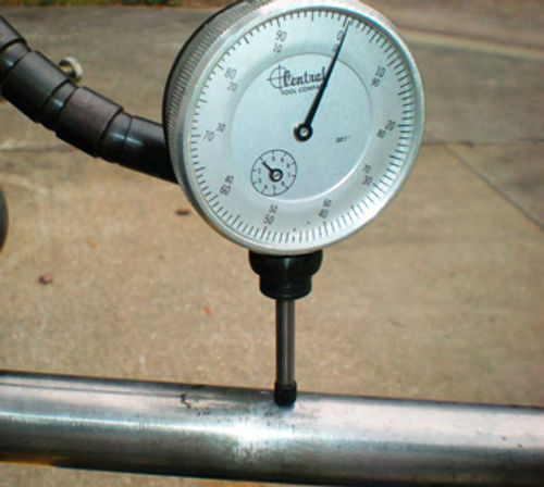
Not knowing the history of the machine, it’s always smart to take an indicator and verify that the arbor is running true as we are doing in Photo 14. Adapters can also be checked in the same manner. Using spacers (or other adapters to act as spacers), snug the arbor nut, and place the tip of the indicator on the edge of the adapter in question and manually rotate the arbor to check its runout.
Next both lathes were placed on a large, elevated flatbed cart in preparation for cleaning and painting. One of those huge drip pans had been placed on top of the cart, and a couple of cinder blocks were used to elevate each end of the lathe and make it easier to service. Photo 15 shows the 4000 in position for cleaning. This puts the lathe at a good working height, keeps it from sitting in any mess, allows access to the motor and underside, and it’s in a perfect position for painting.
Electrical Panels Were Removed
To make the task of cleaning, masking and painting the lathes easier, the side electrical panel that holds the lamp was removed from both lathes. These will be painted separately, but the Hustler held a few surprises. Secured with two screws removal was quick, but wiring also needed to be disconnected to completely free it. This was as simple as removing three wire twist caps. While removing those caps, however, it was discovered that the insulation on the lead wires to the motor was brittle and cracking, exposing the copper wire. This was an unsafe condition, requiring replacement of the wires. Hopefully, the wiring within the motor would be OK, and as the motor had to be removed to replace this wiring, the question would soon be answered. It’s secured by four bolts to a mounting plate that tilts allowing the drive belt to be tensioned and released. The drive belt and both pulleys had already been removed to make painting easier and the opening in the rear of the machine would now be the point of access to remove the retaining bolts.
The motor’s mounting location was marked to make sure it would be relocated in the same position. Three bolts were easy to reach, while, of course, the fourth was a bit of a challenge. While I supported the motor with a pry bar through the opening created by the removed electrical panel, my wife removed the last bolt. You don’t want to take any chances putting your hands underneath it, the motor is quite heavy.
The motor was then lowered down to the drip pan below. Having the lathe elevated on the cinder blocks was perfect as it allowed the motor to be slid out easily from underneath it. The motor looked newer than the machine, possibly it had been replaced at some point, and its wiring looked fine.
Two feet of 12-gauge wire was more than enough, and it was purchased at Home Depot for a few dollars. I wasn’t too surprised to discover the lead wires in the 4000 lathe were also brittle and cracking. While this wire replacement was the same as on the Hustler, the motor mounting had changed slightly over the years, but it was still straightforward. The motors will be reinstalled once the cleaning and painting has been completed.
As is normally the case, the more things are disassembled, the less masking is required, and a more thorough paint job can be applied. So with that in mind, the lamp’s wiring was disconnected and the lamp completely removed from the panel. The Hustler has an electrical receptacle (outlet) in the panel; it was removed, and so was the power switch. All that was remaining was the power cord. The plastic cord lock that snaps into the panel to secure the wire was removed, and the cord disconnected. Suddenly there was nothing to be masked, but there was another surprise. While cleaning the power supply cord, which was thought to be the original, I noticed it was marked 18/3. Someone used 18-gauge wire? That’s impossible; I must have read it wrong. No, that was it, alright. This Is considerably undersized to power this machine. This lathe is rated at 14A and that thin 18-gauge power cord is adequate for little more than a light bulb. A 12-gauge supply cord with a molded plug was the first choice, but only 14-gauge was available. It’s easy enough to purchase the wire and make it yourself, but the molded plug end looks much nicer, and seeing as the 4000 lathe has a 14-gauge cord, I decided to go with it. So another $14 was spent.
With both lathe electrical panels free of all switches and wiring, painting them was a simple task. Once finished, the Hustler’s entire wiring had been replaced with the exception of that going to the lamp. None of the wiring replacement was difficult or mysterious, just time consuming. You hate putting more money into something you are planning to turn around and sell, but when it has to do with safety, there’s no choice.
Lamps Are Commonly In Poor Condition
While different in design, the lamps on both lathes had issues. The plastic lamp housings tend to get beat up, and these were no exception.
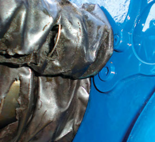
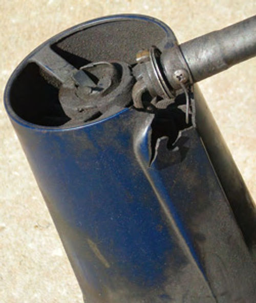
In Photo 15 you may have noticed that the lamp’s shade was somewhat dangling from the end of the neck on the 4000. Some thin wire had been used to hold it in place. A closer inspection revealed extensive damage to the plastic lamp shade that can be seen in Photo 16. It appears as if someone had used it for batting practice. In addition, the neck was also getting weak and not doing a good job of keeping the light positioned, so an entirely new lamp was in order for the 4000.
A replacement lamp (part #907963GP) could be purchased in a nearby community, and while the cost of $90.68 didn’t surprise me, I was hoping to do better. As it turned out there was another option. A few days earlier a monthly flyer from ENCO tools (use-enco.com) came in the mail and they had a “compact task light” on sale. The catalogue photo had a striking resemblance to the one on the lathe, and it was made in the USA as was the original lamp.
Venturing to their website, a better view was available, as well as dimensions that reinforced my feelings it might be the same lamp. Not identical mind you, the flexible neck was only 24” long, about 4” shorter than the original, and the base would need to be modified. Their price was $59.95 total delivered. In other words, about $50 less than purchasing locally once you added in shipping and sales tax. I was willing to take a chance, figuring there would be some way of making it work.
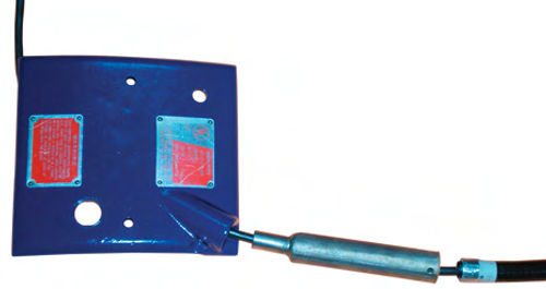
The order arrived in about a week, and the lamp was indeed made by the same manufacturer. The fact that it was black in color instead of blue was of no concern. In order to make it fit into the original lamp’s location the “coupler” was cut off the base of the new lamp, and the original base from the old lamp was removed. It was determined that a 5” section of 3 ⁄4” iron water pipe would work well to extend the length, and act as a union. The base from the original lamp was welded into the bottom, while the base of the new lamp was shaped until it fit snuggly into the other end. A set screw would be needed to secure it, so a hole was drilled and tapped using a 1 ⁄4- 20 tap. Photo 17 shows all the pieces laid out before assembly. The lamp is out of view to the right, what you see is its base. The pipe will be painted to match the lathe, and unless it was pointed out, no one would ever notice. It turned out to be a fairly simple adaptation, and for a moment I had that feeling of genius, that is until I stumbled onto a website offering a replacement lamp for $64.95. Well, when shipping, etc. were added, it would have probably been closer to $80, so there was still some savings, but with the long list of chores to be completed, I probably would have purchased it instead. Lesson learned. There are vast differences in pricing among the many retailers out there, so do a thorough search before making a decision.
On the Hustler the lamp neck was fine; requiring only painting, but the shade had a long crack in it and needed painting both inside and out. This was a comparatively simple repair. Super glue was used to repair the crack, and then heat resistant Silver paint was applied to the inside for the reflective surface, while Regal Blue covered the outer surface.
Next, we’ll paint the lathes, mount them back on their benches and test them by turning some brake rotors and drums.


