
Buying & Owning a Brake Lathe, Pt. 3
Each One Will Be Cleaned, Painted and Attached to a Bench. Then We’ll Prep to Turn Some Rotors & Drums.
Editor’s note: We’ve been busy prepping two brake lathes, one to sell and one to keep. We’ll work on them again this month and then get ready to test the machines by turning a brake rotor and a drum. We’ve run 17 photos in the first two installments of this series, so we’ll start here with Photo 18.
It’s Time to Prepare and Paint the Lathes
Each machine was cleaned with mineral spirits to cut through the extremely greasy areas, followed by a rubdown with GoJo original hand cleaner. Photo 18 shows the Ammco 4000 going first. This should give you a good feel for the cleaning process.
A hot solution of Dawn dishwashing soap and water was used for the final wash, and then it was rinsed. Having the drip pan in place allowed the spent solution to be easily mopped up.
Once dry, it was time to mask. The 4000, a lathe designed to handle brake rotors and drums, has additional boots, locking mechanisms, and the horizontal feed gear box, all of which will require considerably more masking time than the Hustler (another name for the Ammco 7000 disc brake lathe). The Hustler, on the other hand, had been repainted at least once before, and there was paint in places it shouldn’t be, like on name plates, and metal surfaces that should have remained bare. Lacquer thinner on a rag and even a Q-tip removed most of these mistakes. Time was spent carefully masking off surfaces to avoid this happening again.
Painting both lathes went smoothly, with several coats applied. The flat bed cart was easy to rotate during the process so that light would shine from different angles to help avoid missing any spots. In addition, due to the elevation I was able to apply paint while spraying at an upward angle as well. This was a big plus when trying to reach some of the more difficult areas like the louvers in the front of the casting. With the electrical panels reassembled, each was then reinstalled on its respective lathe.
Taking Apart the 6900 Twin Cutter

The 6900 twin cutter is a vital part of each lathe used for rotor resurfacing, and it’s no lightweight:It tips the scale at over 32 pounds. Each tool bit holder has a spring connected at the bottom to retract it. Over time an accumulation of grease, metal chips and dirt will find its way into places it doesn’t belong and gum up the works, making the operation stiff and sticky. The solution is a complete disassembly, cleaning and lube job.
This is pretty self explanatory, and a breakdown of the cutter can be found in the parts identification manual. Photo 19 shows the cutter for the 4000 with all the parts removed. There are two of each item (except the plug), although some parts are specifically right- or left-side.
To the left of the twin cutter housing are the tool bits with the carbide inserts and screws removed; tool bit holders with square head locking bolts; their locating screws with jam nuts; and return springs. (Note: Each carbide insert yields six cutting edges. Rotating it gives you three, and then flip it over for three more.)
On top are the locking knobs and brass plugs.
Below is a plug that fits into the bore for the tool holder.
To the right are the set screws; these secure the “dial plugs.” These plugs are what the shafts thread into, andalso have an indicator line for referencing the calibrated dials. In this photo the dial plugs are both still threaded on the dial shafts. Notice their worn finish. After all the other work was completed,the indicator groove in each dial plug was painted with a white paint pen. Once dry,a piece of upholstery thread was pulled taut over this somewhat rough white line, and then secured with tape on each end. The plugs were then sprayed with glossy black paint, and once the thread was removed, a thin precise line was visible.
Look again at the lower dial shaft and you will see a spring washer follows the dial plug, then it’s the calibrated dial and end knob that’s secured with a set screw.
White lube was used sparingly on the dial shaft threads, and contact points between the shafts and tool holders. It was also applied to the brass plugs.
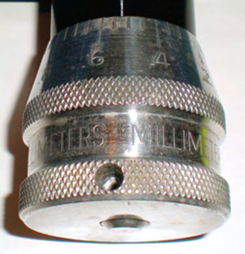
Photo 20 shows one of the micrometer-like dials used to adjust the cutting depth, and the dial plug that was once a worn satin finish is now black. The unit from the Ammco 4000 is calibrated in both inches (.002” increments) and millimeters (.05mm), while the older Hustler’s cutter is only in inches. Photo 21 shows the cutting tool reassembled, painted and ready to put into service.
Note, Ammco has a couple of other twin cutting tools for rotors; a #6950, which is a newer version of this cutter and looks almost identical, and a 7900 cutter which comes standard on more recent 4100 lathes. It has two totally independent cutting bars, and allows cutting rotors up to 4” thick.
Boots Commonly Require Replacing
There was no question that the boots on the Hustler were shot and needed replacement. These were positioned so that the torn areas were facing downward to keep the metal chips from being caught and collected inside. However, replacing these would tie up more money in the lathe, and since I intend to sell it once I’ve cleaned and painted it, I will let the purchaser decide if he wants to replace them.
On the other hand, the boots on the 4000 were marginal but, after all,this is a keeper, so it seemed logical to replace them.
The spindle boot is straightforward. Removing the snap ring frees the end closest to the arbor nut, while simply prying the boot off the lip of the lathe housing frees it completely and allows removal. There is a large bushing that sits inside the front of the boot. Remember to retrieve this as it will be reused with the new boot. A rubber (OEM)style boot was used to replace this. The polyethylene (aftermarket) type is much stiffer, and less flexible, making it more difficult to install. The fact that this boot will remain collapsed most of the time seemed to make rubber a better choice.
At the opposite end there’s an identical boot that protects the other end of the spindle body and a small boot that protects the lead screw. To Replace these first remove the draw bar that retains the arbor. Next take off the spindle lock mechanism. There are two recessed cap screws that retain the satin-finished clamp next to the horizontal feed gear box as seen in Photo 22. This frees one end of the large boot, and by pushing it aside it will expose another recessed cap screw that secures the feed. You may need to rotate the arbor to bring it into view and gain easier access. This cap screw is located close to the feed gearbox, within an inch or so.Remove this, and wind the hand wheel clockwise until the lead screw is completely disengaged. Now some gentle pulling and wiggling will completely free the gear box and the boots can be slid off and replaced. Take a moment to thoroughly clean the threads of the lead screw and its nut, and then re-oil it.
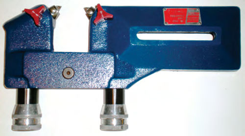
The final boot is the one up front protecting the cross feed. Photo 23 shows the base of the guide foot. Remove both the red locking knob and a set screw above it. Each threaded hole should have a brass plug, and the smaller top one also has a tiny pressure spring. Next wind the cross feed outward as far as it will go until it spins freely. Finally, with the power off, Photo 24 shows me using my right hand to hold the automatic feed lever engaged, while using the other hand to rotate the hand wheel counterclockwise several turns. If it hasn’t been removed before, or has been a while, don’t be surprised if it will take a bit of pressure before it starts to turn, but it will. Now the cross feed is free and can be pulled straight out. Remember not to let those brass plugs and spring get away from you once the cross feed is pulled beyond the end of the guide bar. Before starting on this, have a sufficient space where the cross feed can be placed once removed. This will give you the opportunity to clean out old grease as well as the “junk” that has found its way up through the hollow of the guide foot and into the tube around the feed screw. Make sure to use care and not damage the machined outside finish of the “tube.” Once out, the boot simply slides off. To replace the cross feed, gently get it started by hand; line up the foot, then push it in until it stops. Now wind the hand wheel clockwise and the feed screw will engage and start winding in. Finally, to reconnect the automatic feed simply start the machine, and engage the cross feed lever, and suddenly the cross feed will come to life as though it were re-facing a brake rotor. Remember to replace the brass plugs, spring, set screw and knob and the task is completed.

It’s always a good idea to save your old parts until you’re completely finished with your project. In the event something was accidentally left with one of the removed parts it can be retrieved.
Mounting Them On Workbenches

Joining the Hustler to the bench isn’t particularly difficult with the help of a hoist, but all the fresh paint can easily be marred. A section of foam water pipe insulation was slid over the chain prior to connecting it to the lathe. In addition, a heavy packing blanket was wrapped over the top of the lathe for added protection. It took several lifting attempts until the balance point of the chain was found. The lathe was then positioned above the workbench. Two short pieces of wooden 2x4s were centrally positioned beneath each end of the lathe and the mounting ears were lined up as closely as possible with the holes in the bench top. The blocks of wood gave the needed clearance to remove the bolts, and before removing them, small sections of wax paper were placed under each mounting ear. There certainly would be some repositioning of the lathe, and I figured that this wax paper might allow movement without the lathe digging up the freshly painted top of the workbench. This worked well, allowing the lathe to slide fairly easily, while the translucent wax paper made it easy to line up the mounting holes. The pieces of wax paper were removed just like the earlier blocks of wood by leveraging the machine slightly. Photo 25 shows the finished product. Unfortunately, the extremely worn name plates quickly speak up and say “yes, it’s been repainted,” but still it looks good.
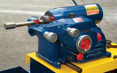
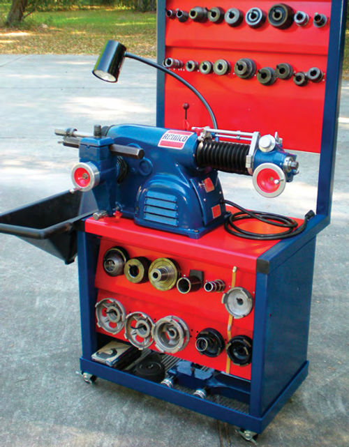
The 4000 was mounted to its bench in the same manner, only extra caution had to be exercised when positioning it due to the top tool board and the rear extension of the cross feed. Photo 26 shows it with all the adapters and chip funnel. The plastic chip collection tray still needs cleaning, but other than that, the job is complete. For added storage a wire rack shelf was set on the angle iron frame base. The open design will help to avoid collecting a ton of dirt and debris, and it’s a good location to store the 6900 twin cutter, and any other large items. I want to keep the top of the work bench from becoming a “horizontal storage space,” and this is a good way to do it.
While not easy to spot in this photo, most of the external fasteners were replaced with ones made of stainless steel. This added about $32 to my investment, but it was the equivalent of putting chrome wheels on my vehicle. My wife even thought it looked good!
Some Controls Differ From One Machine to the Other
The Hustler’s tool post has two mounting options, allowing this lathe to machine rotors up to 20” in diameter, an advantage over the 4000 lathe which is designed for up to 14.5”
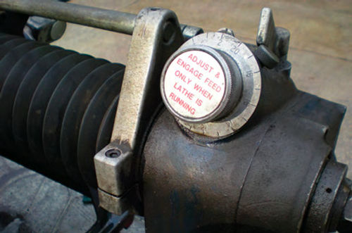
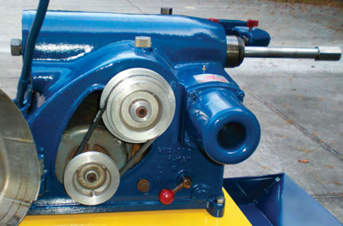
Look again at Photo 25. Below the twin cutter is the large cross feed hand wheel. Rotating this wheel will manually move the cutters inward or outward parallel with the rotor. The red round knob directly below it controls the automatic feed. Pulling outward engages, while pushing inward disengages the feed. The feed speed control knob is mounted on the side of the cross feed near the hand wheel. This is an infinitely variable adjustment from .002” to .006” (amount of cut) per revolution. Rotated all the way inward, as seen here, is the slowest cut. For faster rough cuts the knob is rotated counterclockwise until the desired speed is established. It’s important to note that the speed adjustment (as well as any feed speed adjustment on other machines) must be made while the machine is running; otherwise there is a risk of damage to the mechanism. The only remaining adjustment is the lathe speed. Opening the belt guard door on the back of the lathe exposes three pulley positions as seen in Photo 27. On the Hustler the manual states the speeds to be the following: the inner groove equals 100 rpm, the middle is 150 and the outer is 200.
When it comes to choosing the speed, naturally it will depend on what you are working on. A small thin rotor would do well at 200 rpm. Heavy truck rotors would be just the opposite and 100 rpm would supply the added torque needed. Many shops set the machine at the slowest speed and it’s never changed. This would also be advantageous to the life of the tool bit. To loosen the belt tension, the red knob and lever near the base of the lathe is rotated clockwise. Once the belt has been moved to the new location, the lever is then returned to the full counterclockwise location. Should belt tension adjustment be required, it’s accomplished by loosening the nut located between the lower pulley and the lever. Complete details on this are covered in the manual.
Time to Run a Test
It’s time to check out the Hustler by turning the rotors from my 1986 Chevrolet Caprice. But before getting started with any project, use a micrometer and check the rotor’s thickness against the minimum allowable thickness shown in your shop manual or stamped on the rotor. Note that some rotors may only show the “Discard Thickness,” not minimum machining thickness.
Small chips will be flying once the cutting starts,so now is a good time to put on eye protection. Safety glasses, goggles or even a full face shield are all good choices. The 6900 cutter is usually pictured in advertising with a Plexiglas shield in place for eye protection. Early on it was an optional component, but on today’s cutters it’s most likely standard equipment.
The middle speed of 150 rpm was chosen. The wheel bearings and hub seal were removed from the rotor and set aside. They will be cleaned and repacked once the machining is completed. Next several paper towels were used to clean the grease out of the hub. The less grease, the fewer the number of metal chips attracted to the area. This also allows for a good inspection of the bearing races that the adapters will be seated against. Two properly fitting double taper adapters were then chosen to center the brake rotor on the arbor. First the large adapter is slid on the arbor followed by the rotor. The rotor’s large inner bearing race is guided up onto the adapter, and while holding it there the smaller adapter is slid onto the arbor and into the small bearing race. Now comes the spacer collar followed by the arbor nut, and then simply snug it down. If necessary, loosen and visually center the twin cutting tool in relation to the rotor. The long adjusting slot of the twin cutter tool should be approximately parallel with the arbor.
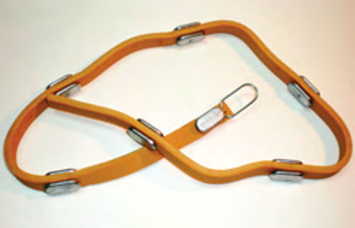
Now it’s time to place the silencer band around the rotor. Photo 28 shows the rubber silencer band (#6920) with lead weights that will be positioned around the circumference of the rotor. Simply wrap it around the vented portion of the rotor, and stretch it until the end can be hooked to one of the lead weights. Ammco also offers silencer bands (#6921 & #6922) for thin solid rotors, as well as a friction silencer (#7075) that mounts to the machine and can be used to dampen solid or vented rotors. If you are wondering what the silencers do, try making a cut on the rotor without using any. The ringing you hear is what these devices control—they dampen vibrations on the part being turned. Trying to turn a rotor without using a silencer belt or other dampening device will yield a very poor, unsuitable finish.
Checking the Rotor Setup
The proper rotor setup is essential. Wind the cross feed hand wheel inward, making sure each tool bit clears the silencer belt and rotor surfaces. Stop somewhere close to the center of the rotor, and then turn the lathe on. Slowly move the left-hand tool bit inward by rotating the adjustment dial until a light scratch is made on the surface of the rotor. Then back the tool bit away from the rotor and turn off the lathe. This will usually create an arc, or incomplete circle. Next, loosen the arbor nut just enough to allow turning the brake rotor 180° while keeping the adapter cones from rotating. You might wish you had a third hand, but all you are trying to do is reposition the rotor while keeping the cones and arbor in their same relative locations. Now retighten the arbor nut, and restart the lathe. Reposition the cutter by again rotating the hand wheel and moving the cross feed inward about a half turn. Once again move the left-hand tool bit inward by rotating the adjustment dial until a light scratch is made on the surface of the rotor. Then back the tool bit away from the rotor and turn off the lathe. The scratches should be side by side or very close to it. If they are, the rotor is now ready to be turned. If, however, the scratch marks are opposite each other, there’s a problem. Remove the rotor and inspect the bearing races for looseness or foreign material trapped between them and the adapters. Also inspect the adapters and verify they fit properly on the arbor. Make sure the adapters and arbor are free of nicks or burrs…a stone can be used on the arbor as well as adapters to dress off any small nicks. If the machine’s arbor hasn’t been checked for runout, set up an indicator and verify it’s true as was done in Photo 14. Once the problem is corrected and two scratch marks can be made side by side, the rotor is ready to be turned.
Also, if the scratch you make forms a complete circle around the rotor, it’s running true and is ready to be turned.
Next, we’ll turn a brake rotor and a drum and discuss important points to consider when purchasing a lathe.


