
Buying & Owning a Brake Lathe, Pt. 5
Similar Looks Don’t Always Mean Identical Operating Features. That Was Obvious When He Attempted a Repair.
SINCE MY LATEST brake lathe purchases—chronicled in the October-January issues—I have kept a watchful eye on what else is out there for sale. For example, there are accessories that I would love to obtain, but buying them new can quickly get expensive. Murphy’s Law comes into play in these matters as well. Buy it new, and you will be sure to find a good used one the following day for next to nothing.
Furthermore, I have found that interesting accessories often are packaged with a lathe for sale and seldom will owners sell them separately. Because of this, I ended up purchasing another Ammco Brake lathe. The price was very attractive, so in addition to obtaining the accessories I wanted, there was the potential to clean up the lathe and make a few bucks in re-selling it as well.
My Latest Acquisition
The machine is actually a #3000 (drum lathe) that has been factory upgraded to a #4000 (drum/rotor combination machine) seen in Photo 1. This machine looks almost identical to the #4000 that was the focal point of the above-mentioned series on “Buying & Owning a Brake Lathe, Pt. 1-4.”
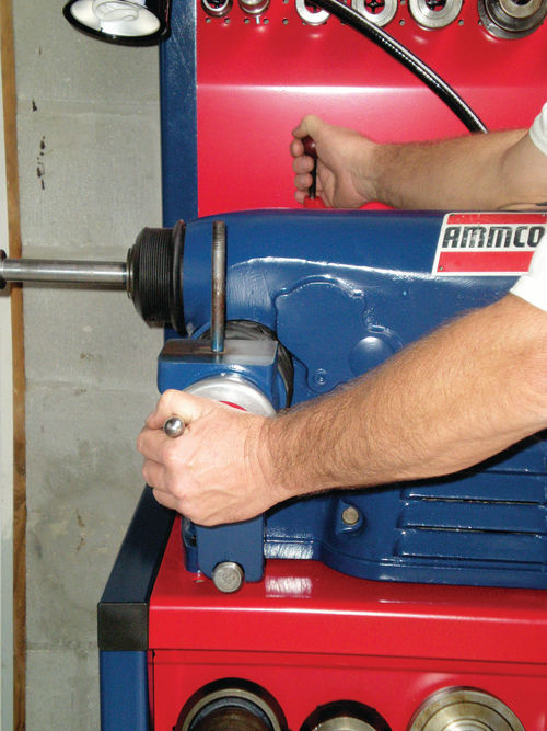

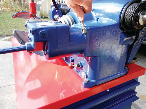
There are two big differences, however. This machine is made of cast iron, and the casting date indicates it was made in 1965, making it 21 years older. So where am I going with this? In the process of “fixing up” and replacing the boots on this machine, the procedure was the same until it came to removing the “cross feed.” Photo 2 shows the method of removal used on the 1986 model #4000 aluminum bodied machine. While using my right hand to hold the automatic feed lever engaged, the cross feed hand wheel was rotated counterclockwise until it spun freely. Initially it took a bit of pressure before it released, but once it did the cross feed was free to slide completely out.
When it came to the older lathe, this same procedure was tried, but it wouldn’t budge. To be sure I gave it several attempts, but no luck.
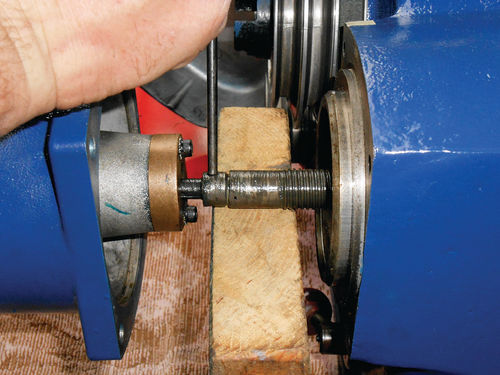
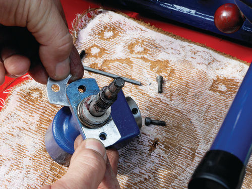
Ultimately, the cross feed gear box assembly had to be removed. Start by removing the plastic cap from the end of the metal tube that extends behind the gear box. This tube protects the extended drive rod that links the gearbox to the cross feed threaded shaft, and finally the hand wheel. Wind the hand wheel clockwise, completely inward and an Allen head cap screw should be visible in the end of the tube as seen in Photo 3. A 5/32” Allen wrench will remove it and the washer behind it. This bolt and washer act as a stop that prevents the rod from accidentally being drawn completely through the gear box, which would ultimately have required taking the gearbox apart to get it all back together. Next wind the cross feed hand wheel counterclockwise until you feel the threads disengage, but don’t try to pull it out. Now remove the four retaining bolts as seen in Photo 4. Once the bolts are removed, have an assistant hold the gear box in place, keeping it pushed lightly against the face of the machine (it’s actually very light, so this isn’t difficult). From the other side you simply push the cross feed inward, toward your assistant. This will push the gear box away from the machine while your assistant offers some slight resistance as well as visual aid. You only need to push the cross feed in a few inches until the threaded shaft and bronze nut are visible. The gear box is then pulled back slightly, just until the union between the drive rod and threaded shaft becomes visible as seen in Photo 5. As you can see in the photo the union collar is only sticking out about an inch beyond the bronze nut. To be safe, keep this union as close to the bronze nut as possible, and while supporting it with a block of wood, use an 1/8” drift pin to tap out the roll pin as I am doing in the photo. You don’t have a lot of excess room to play with, and should you move the gear box away too far, the drive rod will completely pass through the drive gear, and the gear case will have to be opened up to reposition it. Yes, I found that out the hard way.
Once the pin is removed, the gear box can be set aside, and the cross feed slid out. Of course on this machine there was cleaning and painting to be done, and then the boot was slid on and the cross feed and the roll pin replaced. A pair of Vise-Grip style locking pliers worked well to gradually squeeze the roll pin back in place. The gear box is slid forward over the drive rod until the bronze threaded bushing contacts the threaded rod, and then the hand wheel is slowly rotated clockwise until the threads have completely engaged. Next push the gear box up until it meets the mating surface of the lathe, and the four bolts can now be replaced.
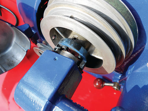
Pay attention to the angle drive that links up to the top “driven” pulley so that it’s centered up properly. There is some slight rotational movement in the gear box that will allow some adjustment. Should you notice that the angle drive isn’t concentric with the center of the pulley, (as this machine wasn’t) shims can be purchased from Ammco, or made to space the angle drive away from the gear box allowing it to be better centered with the top pulley. The manual shows shims available in .005”, .010”, .020”, and .030” thickness, and combinations can be made if necessary to make certain the angle drive is centered and running as concentric as possible with the pulley. The 1986 #4000 lathe didn’t need adjustment or shimming, but this older machine did. Some .035”aluminum flat stock was used to form shims and space the angle drive away from the cross feed gear box as seen in Photo 6. Had this not been done, the operation would be noisy, and unnecessary wear (which was already quite evident) would occur to the pulley drive disc. This drive disc (part #9818) simply bolts onto the end of the driven pulley with three cap screws, and is easily replaced if it’s too badly worn. Try to obtain equal air gaps between the drive disc and the angle drive. Photo 7 shows all in position, and properly positioned.
I don’t know when they changed the drive rod on these machines, but it’s safe to say if you are working on one and the cross feed can’t be freed by the procedure shown in Photo #2, you most likely have a roll pin that will need to be removed as was necessary on this machine.


