How -to Automotive Lighting, Pt.1
No One Doubts the Importance of a Good Lighting System. We’ll Start With Tips Regarding Your Headlamps. b
WHEN DRIVING AT night, it doesn’t take long to get the feeling that you’re surrounded by vehicles with lighting problems. Is That a motorcycle coming at you or a car with only one working headlight?Does that vehicle have its high beams on, or are the lights out of aim? Moreover, these types of problems can range from the headlights to the tail lights and include everything in between.
Since we want to do our part to help reduce these potential hazards, in this series we will cover various topics including the replacement of bulbs and headlights, different methods of aiming the headlights; checking and troubleshooting some of the more common problems with headlights, brake lights, directional signals and flashers, and we’ll review the applications of some of the special tools helpful in performing these services as well.
But before we get to work, here are a few helpful definitions to keep in mind along with a list of some of the necessary tools and supplies.
Some Electrical Terms
Open Circuit: A break or opening in an electrical circuit which prevents the flow of current. A blown fuse, broken wire or an uncoupled connector are all examples.
Short Circuit:to provide a shorter electrical path instead of following the prescribed path. An “unwanted copper to copper connection” such as within a winding, or two wires contacting each other in a harness.
Ground: the return path of current to the battery. This Is commonly through the frame, engine or connected sheet metal components. When referring to an electrical defect it’s considered an “unwanted copper to iron connection,” such as worn wiring insulation allowing a wire to make contact with a grounded surface.
Voltage Drop: the amount of voltage lost when current passes through a circuit due to resistance.
Some Helpful Tools & Supplies
Digital Volt/Ohm meter, test light and a jumper lead extension, soldering gun and solder, heat shrink tubing, liquid electrical tape,rubber/self fusing electrical tape, needle nose pliers, magnetic tip screwdriver with assorted tips, long shaft Phillips screwdrivers, Bulb Service Kit, JB Weld, Shop Manual.
Headlights
Now, let’s start our project at the front of the vehicle with a discussion regarding its headlights.
Most vintage vehicles are equipped with sealed beam headlights, where the filament(s), reflector and lens are one sealed unit. Although they are made in various configurations, most of us will likely be dealing with this type of headlight.
The lenses of these lamps are embossed with either a number 1 or 2. The number “1” indicates a single filament and is the high beam. The number “2” indicates dual filaments and is a combination of low and high beams. A number 2 lamp may be the low beam of a four-lamp system, or the single lamp used in a two-lamp system.
There also may be a letter with the number, but I wouldn’t be too concerned about it. An “A” marking, for example, should indicate rectangular lamps, but then the lamp’s shape would be rather obvious even without markings.
The majority of vehicles will have either a two- or four-headlight system.
With a two-headlight sealed beam system, each bulb has both a high and low beam. In a four-light configuration, two are strictly a high beam; while the other pair is a combination of high and low beams. In the low beam mode, only one pair will light. Now click the headlight dimmer switch and the second pair of lights will come on yielding a high beam, while the low beams will change to their high-beam mode.
Some later-model vehicles using halogen bulbs that plug into composite headlight housings work differently. One pair is used for low beam only. When clicking to high, they turn off and a second pair of high-beam-only lights will turn on.
Headlamps can fail in several ways:
1. They can simply burn out. If the bulb is the low beam, it can fail to work on low, but still work on high, vice-versa or quit completely.
2. Bulb(s) may become dim. There usually is a very noticeable difference in intensity between opposite bulbs. This could be the result of a bad bulb, or a poor ground connection. If both headlights are equally dim, you may have a problem with the charging system. It could be as simple as a loose, slipping belt, or a malfunction with the alternator or voltage regulator. A quick way to check the belt tension is to see if the alternator pulley can be rotated by hand. If so, the belt is too loose. And, finally, don’t rule out your headlight dimmer switch, but the chance of it being the problem is extremely remote. That scenario would also affect the headlights in pairs.
3. A low beam that remains on high all the time. I encountered this situation on two different vehicles. I thought the light was out of aim, but that was not the case. Clicking the dimmer switch made no change in the bulb’s intensity. In each instance, replacing the car’s lamp fixed the problem.
Headlight Replacement
It’s generally recommended to replace headlights in pairs, either both low or high beams. The thought is that if they are all the same age and one becomes a problem, the opposite headlight won’t have that much life remaining and there also can be an intensity difference between the old and new bulbs.
There is equipment made specifically for checking headlight intensity, but unless you are running a state inspection station, I don’t see the need. For those who may be curious, if you can find an old photo exposure meter, it can be used for making comparisons.
Lamp removal fairly simple, but exercise caution just in case the sealed beam unit has been cracked. You may not readily see the damage, but protective gloves can help you avoid a cut hand.
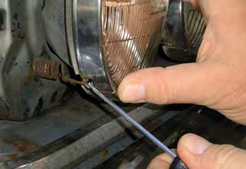
To begin our replacement process, the headlight bezel must be removed. These usually are retained by several screws and some, like the one seen in Photo #1, have tabs on the bottoms that match up with corresponding slots. Other bezels may be as simple as a ring with one screw. Many headlight fixtures use a spring to retain the ring around the sealed beam and help anchor the headlight bucket. This spring must be released to remove the retaining ring. (Photo 2 shows a typical example.)
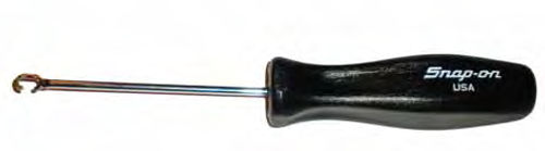
The tool in Photo 3 was popular in the 1960s and ’70s and was made specifically for releasing this spring. This one is no longer made by Snap-On, but a pick tool with a curved end would likely do. Later rectangular lights only require the use of a screwdriver to remove four screws that retain the headlight ring. (A magnetic tipped screwdriver is very handy for headlightservice asit will help you avoid the loss of those small screws.)
Once the bulb is free of the stainless steel retaining ring, it can be unplugged and replaced with a new one in the reverse order.
Headlight Adjustment Screws
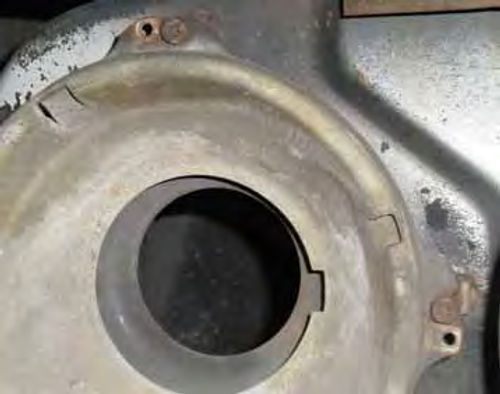
With the headlight removed, the two adjustment screws are plainly visible (Photo 4). The top screw is the vertical adjustment and the one centered on the side is the horizontal. These shouldn’t be turned unless you are prepared to check and aim the lights (which we will cover later). If your headlight bezel is designed to allow access to the adjustment screws, it will confirm their locations should you be unsure.
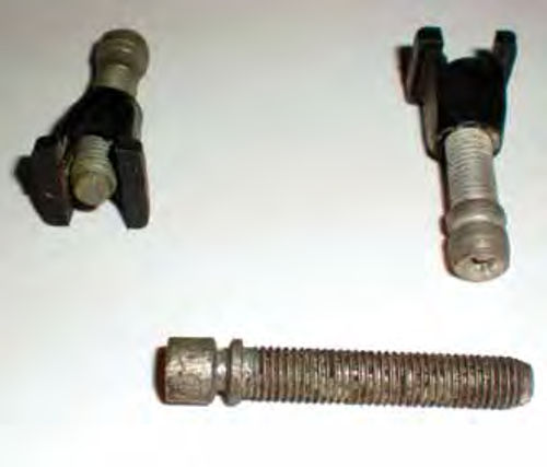
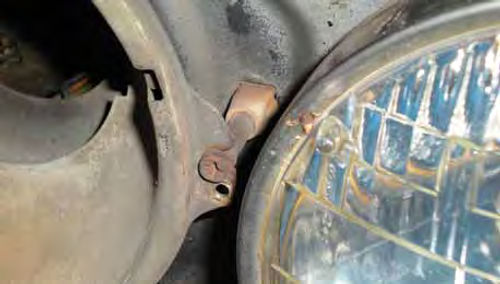
This is a good time to inspect the adjustment points. Usually corrosion isn’t a problem, but the plastic or nylon threads that the adjuster screws into are subject to breakage. Photo 5 shows typical plastic adjuster nuts and the special screws used. The groove near the top of the screw head is where the headlight bucket “rides.” Photo 6 shows a close view of one installed. If any of these are broken, cracked or ready to break, replace them. They should be available at any auto parts store.
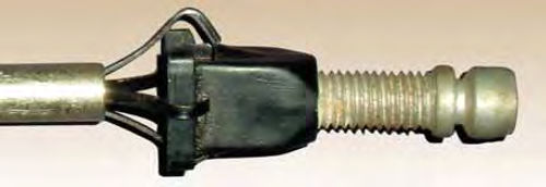
This adjustment part hasto be installed from the back side, so start it through the hole, give it a pull and it will snap in place. In some instances, this may seem like an impossible task due to the location. You may need the aid of “mechanical fingers,” also known as a “pickup tool” (Searssellsthemfor $7;Craftsman #41322). As Seen in photo 7, use this tool to hold onto the new adjuster and by fishing around you can eventually get it to its location without having to take the vehicle apart. Once replaced, headlight aiming will be required.
If your vehicle has adjusters that thread into steel instead of plastic, definitely lubricate them at this time. Any good penetrating oil will do the job.
Some Quick Wiring Checks
If you are experiencing a dim headlight or have reason to suspect a wiring problem, now would be the time to make a few quick tests.
The low (sealed) beam socket has three female connectors in it. Two are parallel, and one perpendicular directly above. The ground connection is on one side, opposite it is battery positive current for the high beam, and the perpendicular connector above is the battery positive for the low beam.
The high (sealed) beam socket has two connectors that are parallel to each other. One is the ground, while the other is battery positive for the high beam.
On 6-volt systems, use a test light, and by activating both the high and low beam modes verify the socket configuration.
A voltmeter is used to check voltage drop (loss). This is actually a measurement of voltage lost due to resistance in a circuit. Analog type voltmeters that have a low scale in millivolts (thousandths of a volt) can be used as well as digital meters. I still have an old Radio Shack analog unit with a .25-volt scale. Its low scale is calibrated in increments of five thousandths of a volt. This will work if needed. When using an analog voltmeter, remember correct polarity is a must or no voltage reading will be obtained. A digital meter, on the other hand, would simply read in negative voltage if connections are reversed.
The following are tests performed on a 12-volt negative ground vehicle.
Voltage drop (loss) on the ground side: Set the voltmeter to its lowest DC volts scale (many digital meters automatically choose the scale for you).
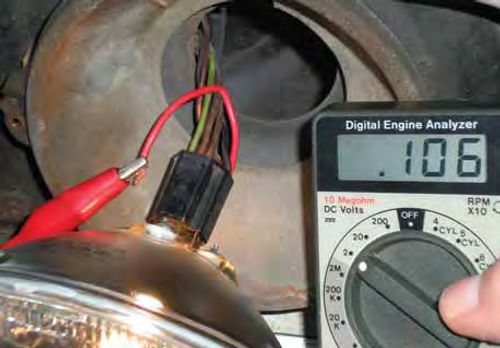
Connect the negative lead of the voltmeter to the negative battery terminal. (On positive ground systems, connect the positive lead to the positive battery terminal.) If your test leads have alligator clips on the ends, connect a short piece of wire to the remaining test lead. Photo 8 shows this configuration being used to back probe the headlight socket’s ground connection. With the lights turned on you should have a reading of no greater than 130 millivolts. Repeat this test for any headlight that is suspected of a wiring problem. Readings that are too high are usually due to poor, rusty connections or deteriorated wiring. As previously mentioned, a dim headlight can often be attributed to a poor ground.
Next let’s measure the voltage drop on the current supply side. Set the voltmeter to the 2-, or 2.5-volt DC scale and connect the positive voltmeter lead to the positive battery terminal. (On a positive ground system, connect the negative test lead to the negative battery terminal.)
With the headlights connected and turned on, use the remaining test lead to back probe the headlight socket’s current supplying connection. This is performed the same way as the test on the ground side. The reading should not exceed 0.6 volts. If yours is a 6-volt system the reading should not exceed 0.3 volts. (In other words, the reading should not exceed 5% of battery voltage.)
Repeat this test for any light in either low or high beam mode that’s question able. In some instances, these tests can be made from under the hood without the need to free the headlight from its mounting. I was able to reach both the low beams but not the high beams on my Chevelle.
A reading that is too high is likely caused by a loose, corroded or poor connection. Close inspection of the light socket itself and any junction boxes is a good place to start. Ancient wiring as well as the headlight and dimmer switches can also equal high-resistance readings. Note, however, that problems with these two switches would yield voltage loss to the lights in pairs, not just one lamp. If your readings are too high when making these tests, backtrack the wiring and perform the test again until the high resistance has been found. Unless your meter has unbelievably long test leads, at some point you will need to use an extension “jumper” lead to reach the battery terminal.
As you well know, moving parts do wear out, so let’s continue with dimmer switches followed by headlight switches. This sequence may seem backward, but in most cases the dimmer is easier to access and will confirm several things once it’s investigated.
Dimmer Switch Mechanisms
Power from the battery is supplied to the light switch, and once activated goes through the dimmer switch to supply power to the headlights.
The most typical dimmer switch malfunctions are:
1. Working in one mode only.
2. Momentary absence of light (total darkness) when switching between highand low-beam mode
3. No lights at all.
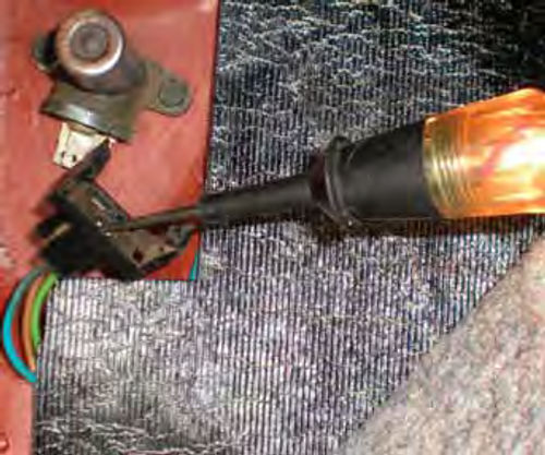
Many of us have floor-mounted dimmer switches, a very practical location, but it also makes them subject to dirt from the environment and subsequent failure. A floor-mounted switch is straightforward, and not difficult to change.
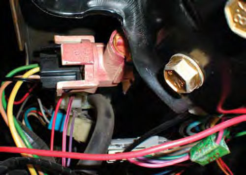
Column-mounted switches ended up taking their place. Hidden behind the steering column support brace seen in Photo 9 is the dimmer switch on my ’87 El Camino. It’s connected by a rod extending down from the directional signal lever and is typical of GM vehicles of that era. Replacing one of these switches usually requires that the support brace be disconnected and the steering column allowed to drop. This is more difficult than the floor-mounted type, due mainly to its small screws that are a challenge to reach. Some later vehicles (Ford for one) used a “multi-functional” directional signal switch where the dimmer is incorporated into it.
There are also automatic-type dimmers that sense oncoming headlights. If your vehicle is equipped with either of these, check your service manual for your specific application.
Testing for a defective dimmer switch:
Dimmer problems will affect your lights in pairs; either high or low beams, but not just the right or left side.
Both floor- and column-mounted switches are tested in the same manner. With the headlight switch in the “on” position, there should be current flowing to the dimmer switch. Using a simple test light, connect the alligator clip to a good ground. With the Chevelle Floor Mounted dimmer we should have current entering the switch from the top wire connector.
In the low-beam mode, current should exit the lower left blade while in high mode it would be the lower right. The column-mounted switch in Photo 9 has current from the headlight switch entering through the yellow wire (the connector that is located closest to the steering wheel). The plug configuration is like that of the floor-mounted switch. Your wiring may be slightly different, but when the headlight switch is on, you should have at least one wire with voltage. In Photo 10, the test light confirms the dimmer receiving current from the headlight switch.
If you are experiencing “No Headlights,” you can now eliminate the headlight switch, unless it is an intermittent problem. Most Likely a defective dimmer switch is the culprit. The switch can be tested with an Ohmmeter or better yet use your test light and the voltage from the connecting plug.
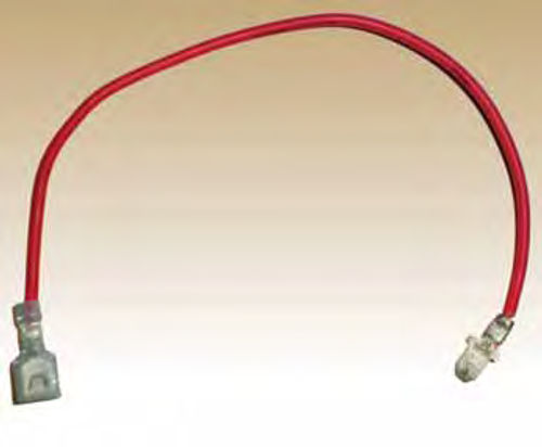
On the floor-mounted dimmer I was able to pull the connector slightly loose from the dimmer switch, allowing me to carefully probe the spade connectors for current flow while all remained connected. If this can’t easily be done, make a jumper wire like that in photo 11. Plug one end into the power supply wire, and the other to the corresponding spade terminal of the switch. The jumper wire shown has an insulated end. This is a good idea since we will have battery voltage passing through it and this greatly reduces the chance of accidentally contacting ground. If you wished to go a step further, incorporate a fuse into this jumper wire for added safety.
Now, with the headlight switch on, while supplying voltage to the dimmer mechanism, check for voltage at either spade terminal. Click and check again. You should have current going through it, and the path should change when it is clicked. If the switch tests good, and it’s receiving current but you still have no headlights, you are looking at a wiring problem in between the dimmer and headlights. It may be an open circuit in the power supply wire(s) or an open ground. Unlikely but not impossible, all the headlights are burned out (you would probably win the lottery first).
Next,we’ll troubleshoot the headlight switch, aim the headlights and do some work with brake lights, flashers and directional signals.