How -to Automotive Lighting, Pt.3
A Mechanical Device Comes In Handy for Aiming Headlights. Or, You Can Try a Quick Check on a Misty Morning.
EDITOR’S NOTE: LAST month we were just beginning to discuss mechanical headlight aimers and we’ll pick up here with adjustment methods. There have been 17 photos in the series so far. We’re reprinting Photo 16 for this installment and then we’ll be moving on to Photo 18.
Adjusting the Mechanical Headlight Adapters
To adjust the rods for your particular fixture always start by setting the inboard rod at zero (this is the guide point on each lens closest to the vehicle’s center).
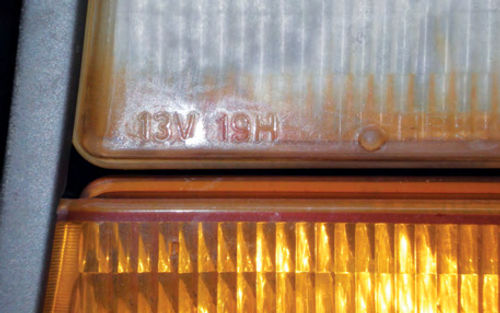
There will be numbers on the lens either next to the guide points or on the lower edge of the lens as seen in Photo18.This one reads 13V-19H.“V” is your vertical adjustment or top rod while “H” is the horizontal or only remaining (and outermost) rod. By pushing and turning these rods, each can be set to the numbers designated on the lens.
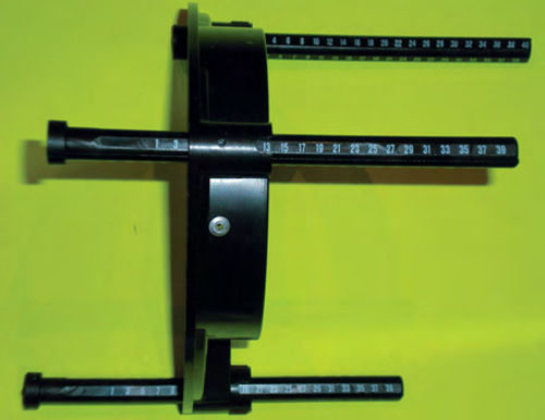
Photo 19 shows a closer view of the large universal adapter that has been properly adjusted for the 13V-19h Headlight. You can tell by noting the rod adjustments (specifically the inboard rod) that this adapter is set for the right headlight. Now repeat this for the other side, remembering the adapters should be a mirror image of each other.
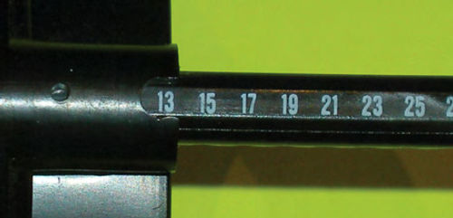
Photo 20 gives you a close-up of an adjustment number. Should you want to use this adapter on a large rectangular or round sealed beam, all rods would be set at zero, and no suction cup extension is needed.
Some Shopping Tips: If you consider purchasing used equipment, make sure that the suction cups on each unit are smooth and the rubber is soft. This is something that might be overlooked. If you see small bumps in the suction cups, they will need to be replaced. (They may appear to hold onto the lamp, but they just won’t hold on long before falling off!) Parts are available and replacement simple, but that means added cost.
Next would be to look at the mirrors and level vials for obvious damage, and the general overall condition. Does the equipment look used or abused? The equipment pictured here cost me around $75, which included the cost of two new suction cups.Remember,it’s always better to have the extra adapters that you might not need now, but wish you had later.
Check Before Using
These aimers are very easy to work with, but always check their calibration prior to using them the first time. All adjustments are accomplished simply by centering a bubble in its level vial and uniting a split image. This is true whether calibrating the units; calculating floor slope compensation; or checking and making the actual headlight adjustments.
Each aimer has three knobs on top and an open window at the rear. Take another look at Photo 16, paying attention to the controls on the aimer in the top of the photo. (We’ve reprinted it this month on page 9.) The first (closest to the suction cup) is your floor level dial, which allows you to compensate for floor slope. If you perform headlight aiming in the same location all the time this will be set once, and never require further adjustment.
The dial centrally located is the vertical dial. Rotating this will reposition the level bubble and give a corresponding reading in inches. This Is used each time when checking a lamp’s vertical adjustment, and when checking unit calibration. The last dial operates the split image rangefinder and is referred to as the horizontal dial. This is used for checking horizontal lamp adjustment, unit calibration, and also in obtaining floor slope measurement. Windows for viewing the split image are located at the top rear and end of each unit. The end window is only used when determining floor slope, while the top is used for all else. The lower portion of the same photo shows the unit’s side view. Here you can see the yellow-and-black target that is used in conjunction with the rangefinder. The white lever on the bottom is for drawing the suction cup back and creating the needed vacuum. Note the small trigger in the handle. Squeezing this releases the vacuum, allowing the unit to be removed from the headlamp.
Calibration In Brief
First attach the calibration fixtures to each unit. Next find a single-pane glass window in your home or shop that is wide enough to space the units at least three feet apart. Remember this must be one piece of glass. Attach the units to the glass three to five feet apart with the targets facing each other. Set all control knobs at zero and use the calibration fixtures to level them. Anytime you are using the control knobs make the final turn in a clockwise direction. This removes any backlash in the units for an accurate reading. Now look at the vertical level bubbles. If they are both centered, great! If not, adjustment is accomplished through the small window in front of the vertical dial with a .050 Allen wrench.
Next look down through the rear window in each unit and view the target. This Is a black vertical bar with a yellow background as seen in Photo 16. If it appears as one, you’re done. If it is split and not aligned, adjustment is needed. There is a screw on the side of each unit and with a small flat blade screwdriver adjustment is completed.
Floor Slope Compensation
Again the calibration fixtures are attached to each unit. The unit that is marked “A” on the end is placed at the center of the rear wheel, while unit “B” is placed at the center of the front wheel. The units must have the targets facing each other. As you might suspect, use the calibration fixtures to level them. Looking straight down through the window in unit “A” (at the rear wheel) you should see your yellow/black target. Turn the horizontal knob until the split image becomes one. If it already appears as one, turn the knob to split it, then, reunite the target again. Remember, as mentioned earlier, always make your final adjustment in a clockwise rotation for accuracy. Whatever reading you obtain on the horizontal dial, transfer this to the floor level dial on both units. You don’t need to be concerned about the settings on any of the other dials since they won’t affect your floor calibration. Just make sure the units are leveled by use of the calibration fixtures, so the only reading you will be concerned with is what is on the horizontal dial of unit “A”.
Aiming the Lights Using Mechanical Equipment
Make sure the headlights are clean (use glass cleaner and towels). Wipe off the suction cups on both units and install the proper adapters for the lights you are working on. They are designed to fit in only one direction, and the steel contact points of the adapter must line up with the guide points on the headlight or something is wrong. Remember the units must always be set up with the targets facing each other, and if it’s a four-light system you are working on, aim each lamp with its corresponding lamp (both low or both high beams).
Next, with the adapter in place and lined up with the headlight, reach under the unit and push the white handle straight forward to engage the suction cup with the lamp. Hold the unit securely with one hand, while pushing the handle as far forward as it will go, then draw it back until it locks into position. If you have problems engaging the suction cup, you might be lifting slightly on the handle, which will put it into the locked position. The action should be smooth, and that last little push during the engagement is the feel of the suction cup flattening out on the headlight lens. Once the unit is in place, grab hold of it and move it in all directions to make sure you feel a strong bond to the lamp. If that hasn’t happened, try again (moistening the suction cup slightly may help).
Repeat the process with the opposite headlight and verify that both units are in proper contact with the three guide points on each headlight.
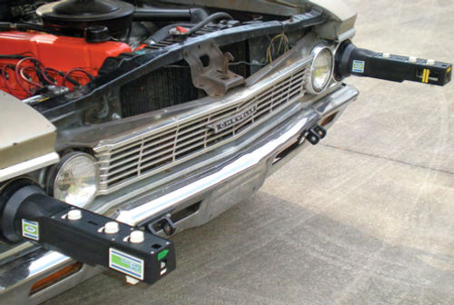
Photo 21 shows both aiming units attached and ready for use. There are a couple of ways to use this equipment, one is to set both the horizontal and vertical dials at zero and see what the target images and level bubbles look like: Pretty close our way off?By lifting or pushing the unit slightly in each direction, you can determine which way the headlight needs to be adjusted to meet the zero settings. Rotate the proper adjusting screws until the bubble is level and the target appears as one.
The other method is to actually obtain readings for each adjustment. Rotate the horizontal dial until the image appears as one then turn the vertical dial until the bubble is centered in the vial. Now you can see the current adjustment position of each headlight indicated by the arrow above each dial. This method is good if you are working with tolerances and are not concerned with them being set exactly to spec. This Is the method a state inspection station would use when checking your lights.
Some helpful hand tools to have are extra long Phillips Screwdrivers and various tips to fit your magnetic screwdriver. Snap-On as well as other professional tool manufacturers make extra-long screwdrivers. These are a big help in making adjustments when the aimers are in place. Once the adjustments are completed, hold onto the aimer, reach under the unit and squeeze the trigger on the handle you had earlier used to engage the suction cup. This will now release the vacuum and the aiming unit can be removed from the vehicle.
Make a Quick Aiming Check Using Your Eyes and the Environment
If you want to make a quick visual check without equipment or a projection chart, do so on a misty evening or morning when it is dark. You will be able to see the actual projection beams of light (much like in the old days with a projector running in a smoke-filled room).
By making a comparison of the beams, you can see if one is considerably different from the other. It is fairly easy to compare beams for vertical adjustment. View your car or truck from the side, probably 20 to 30 feet away and get down where your eye level is about the same as the light beams. (This Is not scientific,so there is no specific distance involved.) The beams of light should appear to be in the same plane and follow the bodyline of the vehicle; if not, adjustment is most likely required.
Horizontal inspection would be a bit more complicated. I have never tried it, but you would likely have to view the beams from the rear of the vehicle while elevated and looking down at them. This could translate into using a ladder or checking it out from a building’s second story. Once again, the beams should follow the side bodylines of the car or truck (at least in most cases) and appear parallel. This quick check won’t assure you that your lights are aimed accurately, but it will let you know if something is definitely amiss.
The Headlight Finale
If your vehicle has composite headlight fixtures, the earlier style that have the guide points, it’s probable they have condensation or even a small amount of standing water inside them. Once you are confident you can re-aim the headlight fixture(s), a repair isn’t too difficult.
First, remove the bulb and then the housing from the vehicle so you can pour out any standing water that’s in the fixture and allow easy access for repair. You can use compressed air to blow out any obvious remaining moisture.
Typically there is a haze built up on the inside of the front lens. To reach in and clean it you can utilize something as simple as a short section of 1/2” PVC (plastic plumbing pipe) with a paper towel folded and inserted into the pipe’s end. Fluff out the towel to cover the pipe end to avoid scratching the interior surface. Glass or plastic cleaner can be used on the towel.
When that task is done, you can remove the remaining moisture with a hair dryer and/or bring the fixture into an air-conditioned (or dehumidified) room. Usually time is the biggest thing,so don’t rush it. Moisture usually enters the fixture from the seam around it, where the reflector portion is joined to the lens. Clean the seam area well and even scuff it with fine sandpaper (this gives a better bonding surface for the sealer). I have had success using both a hard setting sealer like that from a hot glue gun, or a quality two-part epoxy like JB Weld, as well as flexible clear silicone around the perimeter. The glue gun allowed for almost instant replacement of the fixture, while with epoxy or silicone I would recommend letting it sit until it’s cured. Either way, before you replace the fixtures, now would be a great time to deal with the dull haze on the outside surface of the lens. (For more on this, see “Restoring Headlight Plastic” in the July 2007 issue.) Now you can reinstall and aim the headlight fixtures.
As for the newer-type composite housings used on current vehicles, I haven’t noticed any with moisture problems (at least not yet). It would appear they finally are able to seal the housing successfully at the factory. With regard to aiming these new fixtures, you should refer to your shop manual. Most no longer use guide points, so unless the manufacturer of the aiming equipment has created some new tools, I don’t see how it could function on new cars.
Replacing Some Common Exterior Bulbs
Now is a good time to check and replace, as necessary, any exterior bulbs that may be burned out. These can include parking, directional, brake (third brake light bulbs, if applicable) side marker and license plate lights as well as clearance lights on trucks.
If none of your taillights are working (and this is often accompanied by no instrument lights) check your fuses first. If your brake lights are all inoperative, you may have a blown fuse (or possibly a defective brake light switch). Fuse replacement is simple—just remember to use the correct value.
Should the fuse blow again soon after replacement, you will have to find the root cause. The problem could be chafed wiring or worn insulation causing an “unwanted ground.” A problem could exist in one of the sockets themselves. I would first inspect the sockets and nearby wires, and if nothing is found, go back and start at the fuse and work toward the load, inspecting wiring and connections until the problem is located.
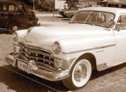
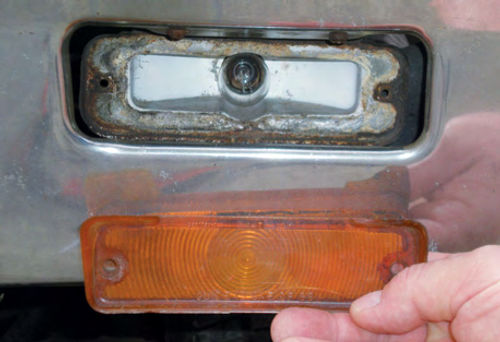
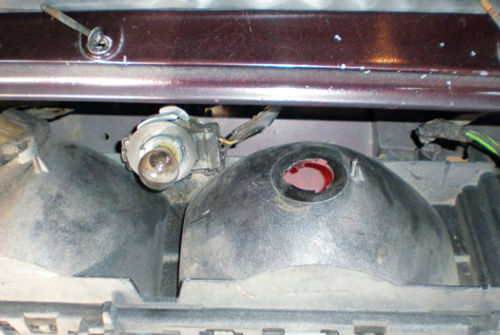
Accessing a bulb to replace it usually is not difficult although sometimes a lens must be removed. This could be straightforward like the front bumper-mounted lens on my Chevelle (Photo 22) or slightly less obvious like the rear fixtures of my Caprice, (Photo 23). Here, three screws at the back edge of the trunk, just at the rear of the gasket, must be taken out and the top of the fixture can be tilted outward. Once this fixture is out, the socket is turned counterclockwise (as looking at the rear of the fixture) for removal and bulb access. Popular with Chevrolets and other GM cars of the ’60s were sockets that plugged into tail light fixtures from inside the trunk. This was convenient—simply pull the socket out and there was the bulb. Photo 24 shows the socket and bulb out of the fixture.
The only problems I’ve encountered with these are that the sockets provide the ground connection for the bulb. The original factory sockets were typically black plastic, and had metal tabs on the sides to complete the ground circuit. An all-metal replacement, while not factory correct, performs much more reliably.
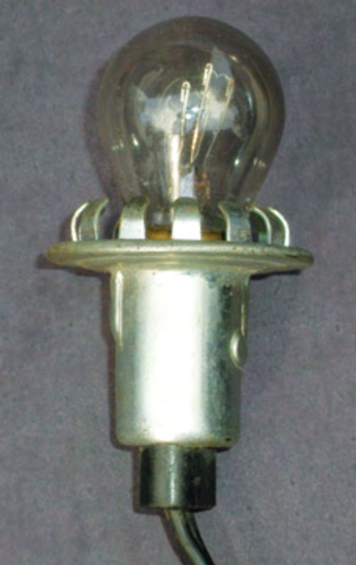
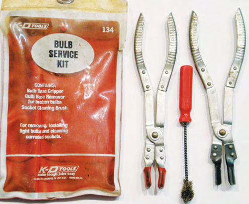
On most older applications the bulbs push in and turn for removal and replacement, and dual filament bulb like the #1157 shown here will only fit in one way. Always be prepared for these bulbs to break when removing them especially if the bulb is badly discolored. Wear protective gloves, use a rag or, better yet, seek out a bulb service kit like the one in Photo 25. This one was made by KD Tools (#134) and purchased decades ago. It includes a rubber-tipped tool for safe bulb removal, a special serrated gripping tool for removing the base of a broken bulb, and a socket cleaning brush.
Needle nose pliers are also good to have on hand for removing a broken bulb base. Use them to grab and hold onto the edge of the broken bulb’s base, then push inward and turn counterclockwise for removal. The side of the bulb’s base will bend inward when doing this. This is normal, so don’t be alarmed. If that’s not enough, go to the opposite side and repeat.
If it still hasn’t come out, try sticking the end of the pliers into the socket, pushing inward and turning. Pay attention to see if it turns. It may be ready to come out, but due to a build up of junk in the socket may not pop forward on its own. Try gently pulling straight out. It should go without saying that you must never activate your light switch when you are involved with this type of broken bulb removal. You can always disconnect the battery ground connection for safety (especially a good idea if you have any very young assistants).
Next, we’ll look at brake lights and switches, directional signals and flashers as we wrap up our series on automotive lighting.