
How -to Automotive Lighting, Pt.4
Let’s Consider Some of the Problems That Crop Up With… Brake Lights, Directional Signals and Flashers.
EDITOR’S NOTE: LAST month we did some headlight aiming and replaced some bulbs. There have been 25 photos in the series so far, so we’ll be picking up here with Photo 26 for the last installment.
Brake Light Switches
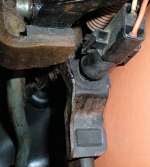
Brake light switches are varied in style and placement. Some earlier vehicles used a pressure switch mounted to the master cylinder to complete the circuit. A friend owns a ’62 Ford Falcon that has this old-style switch (Photo #26). The original master cylinder had a specific port for this pressure switch, but as you can tell in the photo the vehicle has been upgraded to a tandem master cylinder so a tee was used to plumb in the switch.
This pressure switch can also be the source of an electrical drain if it becomes defective. My friend had been experiencing a slow drain on the battery and one evening noticed a very low glow from the brake lights. He replaced the switch and the problem was solved. He also advised me that it is not uncommon for the pressure-type switch to become lethargic. That is, you might make a gentle stop and the brake lights never come on, while greater pressure will still activate the lights—it is likely the switch gets gummed up with age. He also owns a ’65 Falcon Sprint, and it uses a more modern mechanical switch, connected off of the brake pedal.
A typical mechanical switch is mounted up near the top of the brake pedal. The one you see in Photo 27 is on my Chevelle.
Brake light switches complete the current flow when the brakes are applied. If you are experiencing brake light problems, do a few quick checks before you jump in and replace the switch.
Use a test light to see if voltage is present at the switch. It should have voltage present all of the time. If not, verify that you have a good ground connection for the test light and recheck. If Still nothing and the fuse is good, you are likely looking at a wiring problem.
If you have voltage at the fuse, but not at the switch, there is an open circuit somewhere in the wiring between the two. If, however, there is no voltage at the fuse, you have an open circuit in the power supply to the fuse.
All that being said, most of the time it turns out that a defective brake light switch is the problem. You can test the switch with an Ohm meter, or use a jumper wire connection and your test light as we did earlier when checking the headlight dimmer switch.
Depress the pedal (or the switch mechanism) and you should have continuity. If not, replace the switch. Some brake light switches have more than two wires (usually found on cars with cruise control). In that case, check your shop manual to verify which wire receives and carries power to the brake lights. If, however, the switch tests good but you still have no brake lights, you have an open circuit in the wiring from the switch to the brake lights.
Directional Signals
Your turn signal switch mechanism can fail in several ways. Sometimes you will have no option but to replace the switch and its connected harness. Most likely there is someone out there that specializes in overhauling directional signal switches, so if yoursissomewhat on the rare side and a replacement can’t be located, consider checking with club members or do an Internet search before getting involved with any major reconstruction. If, on the other hand, you are like me and own a more common vehicle, there are some repairs that can be made without removal and replacement.
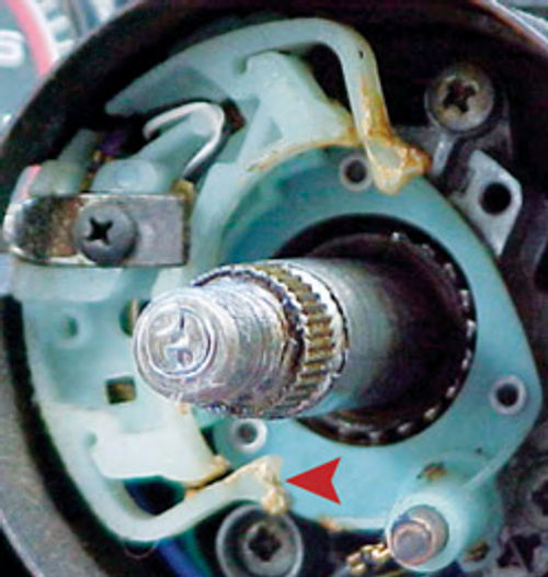
A common problem is the signal won’t cancel when the steering wheel returns. Usually it’s because one of the ears has broken off the cancellation arm.
In Photo 28 the arrow points to one of these two “ears.” If one ear is broken, the arm usually will cancel when turning one way, but not when turning in the other direction. (This will be true unless the problem has existed for so long that the remaining ear also broke off.)
On ’60s Chevys (prior to four-way flashers being incorporated into the directional signal switch), this cancellation arm can be replaced when broken or worn out. The switch mechanism will have to be pulled free from the column, but will not require total harness removal. You will have to disconnect the harness plug connector to allow enough slack in the wire, and possibly loosen the steering column mounting. Now you can remove the switch retaining screws and pull the switch out enough to reach the screw on the bottom side that secures the cancellation arm.
If your vehicle’s cancellation armis not replaceable, see if you can figure out a means of repairing the broken ear. JB Weld (available at hardware, discount and home improvement stores) is a very slow setting two-part epoxy that’s extremely strong. If The broken-off ear is found it can possibly be reattached with this product. If not, try and come up with an idea for creating a replacement—you still have one good one to study.
Regardless, you likely will need to reinforce the repair by adding a splint for support. Evaluate your directional switch and decide if thin brass stock would be a suitable choice. It is very easy to form and work with and is available in various thicknesses and sizes at both hardware and hobby stores. Its cost is minimal but keep in mind that the material is conductive. This is something you need to think about should the repair break later. The concern here is in creating an “unwanted ground” or a short circuit. The switch you see in Photo 28 would be a good candidate for using brass. Other than the contact for the horn button, all contacts are elevated and hidden behind the cancellation mechanism. Other, non-conductive, options would include a wooden ice cream stick or a scrap of plastic.
If you use brass, its end could even be formed and soldered to resemble the broken ear. Possibly a small section of hardwood dowel could be formed and joined to a repair splint. Use something like wax paper beneath the repair to protect the switch mechanism. JB Weld gives you ample time to readjust the repair if necessary—once it’s set, allow 24 hours before testing the repair.
For pressure to hold the repair together during the curing time, consider a clothespin with wax paper where it contacts the repair. It will be obvious that the arm has been repaired, but this will be hidden once the steering wheel is back in place.
The concern here is proper function. Once I had a situation with my wife’s 1967 Impala where the right brake light would not work when we used the left turn signal.
It turned out that there was supposed to be a plastic “stop” to limit the travel of the directional lever/actuator but it had broken off. By allowing too much travel, the circuit to the brake lights was opened, thus no brake lights. I repaired this by drilling a small hole where the “stop” originally was and inserting a small sheet metal screw in its place. This was a fairly simple repair once the steering wheel was removed and didn’t require removing the switch.
More recently, with my ’66 Chevelle, I’ve encountered a problem after making a turn when the steering wheel returns rapidly (typical with manual steering). Not only does it cancel one set of signals, but it also activates my other turn signals indicating that I am now turning in the opposite direction. This happens mostly on sharper turns and not all of the time. This can usually be fixed by tightening the same screw I mentioned earlier that secures the cancellation arm, thus increasing the friction. If I didn’t have this screw in my application, I would then try to figure some way to increase the friction, just not so much that it resists clicking off.
A tip: A good plan of attack before you attempt repairs on your directional switch is to see if a replacement is available if you’re unsuccessful. Know your options before you proceed.
Flashers
Another related mechanism that can fail is the flasher.If you find your signals flash normally in one direction but the indicator stays lit or flashes rapidly in the other, you probably have a burned-out bulb.
But,if they all flash slowly, very rapidly or not at all in both directions, it is most likely a worn-out flasher. (The typical flasher is made up of a bimetal spring that conducts current. When doing so it will become hot and bend open, which interrupts the flow thus stopping the signal; the metal strip cools and the cycle repeats itself. This process also creates an audible click each time).
Flasher units usually are tin-looking and cylindrical or rectangular in shape… and it can be difficult-to-almost-impossible to locate them at times.
If your flasher is still able to make a sound, listen for it closely and it will lead you to its location.
If your vehicle also has a four-way flasher, activate it, follow the click and, once found, it can be disregarded in your search for the actual culprit.
Sometimes the flashers plug into the fuse panel, some may be clipped to the inside edge of your dash, and others simply dangle from wires somewhere under the dash. Some manuals will give the locations of flashers so if yours has become silent check there first. Once the flasher located,replacement is usually a simple plug-in much like a household electrical plug into a socket.
The Bulkhead Connector
Finally, one other often-ignored component of a vehicle’s wiring is the bulkhead connector. This is the wiring connector that plugs in from the firewall to the fuse panel—the major connection where the outside wiring meets the interior wiring. Although it’s well-insulated and rugged, age still can take its toll, so always consider this connection when trying to track wiring problems.
Seek Out Helpful Diagrams
As you may have noticed from the photos and references in this series, I am a Chevy guy. On the other hand, your allegiance may be with Ford, Mopar, imports or other vehicles. So realize that your situation may vary slightly and use this text as a general guide toward finding your problem.
As we have discussed, lighting problems can be as simple as a burned-out bulb, a blown fuse, a worn-out switch or it also can take the form of wiring problems such as a poor electrical ground, high resistance at electrical connections or old, worn wiring insulation.
Whatever vehicle you’re working on, tracking wiring problems will not be easy, but the task can be greatly simplified if you know the electrical path to follow. Shop manuals with wiring diagrams will be extremely helpful; Mitchell, Chilton or Motor manuals also are good choices.


